New Hardware #26
Comments
|
My two cents.. Regarding point 3. - separate regulators for each sensor please. However, are we sure about the ferrite after the regulator, like in the original sensorboard schematic? I would expect it to be pre-regulator, to better decouple the regulators from each other, and to not increase high frequency PSU impedance to the sensor? Audio amp - I wanted to suggest the PAM8303 / PAM830 line for consideration as these can be hand soldered, but given that this won’t be possible for a lot of the components you’ve mentioned, it’s probably a moot point (same goes for through-hole electrolytic capacitors). Regarding additional point 2 - I would love this to be able to live inside an OV as a drop-in replacement, but also to be able to exist on its own, feeding airspeed and vario data to XCSoar running on a mobile phone. Regarding additional point 6. - I’ve wondered whether you could get air leakage from a via to a pressure sensor when using bypassing on the bottom side close to the sensor..? |
|
Going through your responses: Ferrites: I don't see any ferrite beads. There are inductors in a Pi filter. I'm not sure that's the best structure. It doesn't help that I literally can find no published inductor values. I do wonder if the Pi filter may be responsible for the blip behavior that I saw. In other words, if it's causing voltage droop whenever you start a conversion, then after doing so many with a fixed interval you will establish a steady state voltage profile, but if you change the timing, it causes erratic results. On the other hand, the time constants seem like they'd have to be awful long. Audio amp: The MAX98304 has substantially lower radiated (and possibly conducted) EMI than the PAM8303. Stefan had mentioned he had tried the Adafruit PAM8302 and found that the EMI did interfere with the VHF transceiver. It is possible that the board could be better optimized to limit emissions, for example, running two filter caps instead of just one. While I realize that soldering modern packages is more difficult, the reason they are used is not just they are cheaper but because they have better performance from a heat perspective and a parasitic perspective. Inside/Outside: I agree it'd be nice to get a board that works both ways... However, the question then becomes what interface if its external? And do you supply 5V or 12V? Bottom/top: Both the LPS22 and the MS5611 have holes in the top of the package. if you do not seal against the hole, there will be leakage. I don't know how the POM block works. Is there a gasket? Is there one hole per MS5611 or 2? If the POM block does seal against the top of the package, I fail to see why components on the bottom would or vias from bottom to top would screw things up. FWIW, Stefan's sensorboard has components on top and bottom. I'd still like to know what the difference between Stefan's board is and the current schematic/layout and if the schematic/layout is available in digital form somewhere -- I'll need it to make sure components are properly aligned with the POM block. |
|
Hi @hpmax please visit www.openvario.org or ftp.openvario.org. |
|
@hpmax I meant ferrite beads as in https://mouser.com/Search/Refine?N=19978750. EDIT - here's the actual part as specified in the May 2016 BOM available in the Downloads section of openvario.org: I can see a Pi filter being useful after a switching regulator to filter out any switching spikes, but here it’s just slowing down the response of a linear regulator. Putting it before the regulator could however help filter out whatever’s going on in the main supply rail. If you have a chance to desolder the inductors and hook up a bench PSU directly to the MS5611s you could see if that has any effect. Might be worth a try. Audio amp - fair enough. It’s hard to say whether Stefan’s interference was caused by EMI or whether it could have been caused by power supply coupling, but if you have a product that has better EMI specs than the PAM chips then why not. Interface - Bluetooth or Wifi, whatever’s available from the ESP32 board that gets decided on. I realise that there’d need to be extra coding involved to get the interface working. I’d prefer 12V input, so that you can power it directly from the glider's battery. I’m using an AP65211 buck converter in another project that accepts 4.5V to 18V input, that might be worth looking at. Bottom/top: You can find photos of the POM block here: https://www.openvario.org/doku.php?id=projects:series_00:mechanics Stefan’s sensorboard looks to be pretty similar to the OpenVario one: |
|
Yeah, that's the first I saw of the BOM which included the actual parts for the "inductor", I agree that's the part listed. Not sure why it was listed as an inductor when it's not. I also agree it would make more sense to put them on the input to the regulator. That said, the datasheet has a maximum impedance of about 1000 ohms resistive. The cap is 100nF. That gives a time constant on the order of 0.1 ms. The blip behavior seemed to noticeably change on the order of 10s of ms of timing jitter. But with 25+ ms, it might as well be DC as far as that filter is concerned. Audio amp - I just bought a Controleo3 and will build it up this weekend (hopefully). Will then build up a MAX98304 amplifier and see how it works. If not I'll go back to the MAX1871. Interface - The AP65211 seems reasonable although my big concern with these switched converters (like the Class D) is noise. A resistor/zener divider could be connected to the enable line, and if installed in the OV, the 5V power from the OV, could be connected to a BJT (or FET) pull-down. I am a bit concerned about the ESP32. I'd like GPS input into this, which would presumably be through USB. It would then have to forward this information to the OV. If it's internal, it could probably be over I2C or SPI or something, but if external, then what? The ESP32-S2 only has one USB, and no BT. The ESP32-E has BT and WiFi but no USB. Regarding the POM block... I think I understand now. Basically it's sealing against the board, not against the top of the component and since the "cave" has an 8mm diameter, I don't think its necessary to put stuff on the bottom. The LPS22 is 2x2mm. If we assume the caps are another 2x2mm that means the total diagonal is only about 4.5mm. No problem. Even the larger MS5611 is still 5x3, which would potentially give 5x4=6.5mm. Is the perimeter supposed to be sealed with PUR? Regarding Stefan's sensorboard. It's clearly missing the audio amp and all related components, but otherwise it's at least close. |
|
The inductor - yes… it may not be related to the blips, like you say; it’s just something I thought worth mentioning when looking at the sensorboard schematic. The interface - are you sure about including the GPS? It opens up a whole new can of worms, while in my eyes providing little extra benefit, given that you’ll probably want to have an IGC-certified logger connected to your OV anyway so that you can declare to it (which will also give you GPS and baro data). On the other hand, if I was to use the sensorboard purely with a mobile phone, I’d be OK with the phone’s internal GPS (but I’d probably have a logger connected to the phone via Bluetooth anyway). Connecting an external GPS to the ESP32 via USB would also be a pain mechanically; I’d probably go for an external I2C interface through a 4-pin RJ connector, although I’m not sure what the susceptibility to interference would be like. Or maybe a 6-pin connector and use the extra pins to add GND wires between the signal lines. The current OV sensorboard has a 6-pin RJ11 connector with I2C, 3V3, 5V and GND, so maybe keep the same connector and pinout. Regarding power - I like the idea of disabling the AP65211 if the board is powered by 5V. I would place a Pi filter after the AP65211 to filter out switching spikes, and have a “clean” and “dirty” supply line, the “dirty” one being taken from before the Pi filter and powering the ESP32, and the “clean” one taken from after the Pi filter and powering all sensors. I’d also place inductors/ferrites in the supply line to each sensor’s regulator. Then you have the question of whether routing the ground returns of the “dirty” supply line to the main filter cap separately from the “clean” supply returns would be more beneficial than a ground plane.. but you could probably eliminate that by component placement (i.e. have the sensors to one side of the PSU and the ESP32 to the other side). You could also place another Pi filter before the AP65211 to help isolate it from the glider’s main power supply line. Regarding the POM block sealing.. I guess it’s “whatever you manage to come up with” ;) Personally, I’d put a thin layer of sealant around the pressure sensor caves to avoid pressure leaks from one sensor to the other, then maybe around the whole block. One other thing I’d also suggest when designing a new sensorboard would be to keep some free space at the sides of the sensorboard PCB for monting brackets, so that you don’t rely on the barbed connectors for mounting the sensorboard to the case. EDIT - It would also be useful to have the 5V from the OV go through the Pi filter after the AP65211 - at the moment the sensorboard shares the same 5V line as the Cubieboard and the LVDS without much additional filtering going on. |
|
If we are putting an ESP32 on the device as Timo suggests we have a fair amount of computational horsepower. I'd like to essentially run it as a full IMU. In other words, I want it not just to go vario and airspeed data, but full AHRS and GPS. It is useful to have access to all of this data in the IMU algorithm. It's not just that AHRS is useful to have, it's that accelerometers or gyros can help more accurately calculate the vario data. The problem with accelerometers and gyros are that they can drift. GPS has zero net drift, and so the GPS is useful for correcting drift in the accelerometer/gyros. It all works together. That's why I want GPS. If you want to hook it to your phone, I presume you want it hooked via Bluetooth? That could be a problem for the ESP32-S2. Bear in mind, whether you are using this with your phone or whatever, this is likely to be a semi-permanent installation in the glider. Not only do you have to have it hooked up to the plumbing system, but you are also should be calibrating the installation for pretty much every sensor, and the magnetometer and acceleratometers are definitely going to require a rigid and fixed attachment point to the aircraft. Regarding your filter, seems reasonable. Essentially we are talking about having two power supplies, the 12V-5V (although perhaps 4V?) which is bypassed if inside the OV and then the linear regulators, of which we are having a bunch. You are proposing putting one in front of each regulator except the regulator that drives the ESP32. Please bear in mind we don't have infinite space. I'm kind of pushing the components around in Eagle, and I'm near full capacity. I can probably fit everything in, but we can't just keep adding and adding. |
|
GPS - Ah, got you. In that case, yes. However, as far as I’m aware, AHRS, etc is only implemented in XCSoar as proof-of-concept and isn’t fully functional, so I don’t know if the sensor fusion you’re proposing is something you can take on. In any case, the ability to connect a GPS is probably worth having for any future development in this area. Regarding connecting to a phone, either Bluetooth or Wifi’s fine for me. I’m currently interfacing to a logger via Bluetooth, which would mean I could keep the phone’s Wifi turned off to save a bit of power, but I’m running the phone off a power bank anyway, so it’s not really an issue. I’m OK with a fixed installation in the aircraft - like you say, it’ll be needed for the plumbing anyway. Yes on the power supply - one switching regulator, several linear regulators for the sensors except for the ESP32 (unless you decide on the Wifi-only ESP32-WROOM-32E, in which case you’ll need one). Not sure about 4V off the switching regulator, maybe keep some headroom for the filtering and for the LDOs to have something to work with? The dropout’s pretty low, so up to you. If you’re tight on space then I guess we could skip the input Pi filter, but I think keeping the post-regulator ripple filter is a good idea. |
|
The sensor fusion is best done earlier in the chain. Right now, we have a Kalman filter on the TE sensor. Wouldn't it be better to do a Kalman on all the sensors simultaneously? That's a huge deal actually. Remember, assuming the dynamic data doesn't change, TE and static should be changing together. Which means, you can substantially improve the performance. by merging those. You don't want to do Kalman on top of Kalman on top of Kalman because it becomes much harder to understand the dynamics. USB seems to be the current gold standard on how to connect to GPS. Another question is... what about audio? Should the sensorboard produce its own audio? |
|
Sure, if you can do the sensor fusion on the ESP32 and output only the result then that’s probably best. What USB GPS modules are you considering, and do you plan on connecting them directly to the ESP32’s micro USB connector? I’d have concerns over the long-term reliability of the connector what with the vibration and everything, but I guess if it’s a fixed installation it shouldn’t be as much of an issue as if you were constantly plugging and unplugging the cable. Audio… good question. The big question for me is, how will you control the volume? If you can interface a dedicated rotary encoder to the board through a 4-pin RJ connector and have the board space for it and also the audio amp and connector then that’s awesome and would make the next-gen sensorboard a very useful stand-alone unit. A dedicated volume control is pretty important in my opinion; I also like the idea that you could place just the encoder on the instrument panel if you’re tight on space and run a cable to the sensor unit which could be located elsewhere. |
|
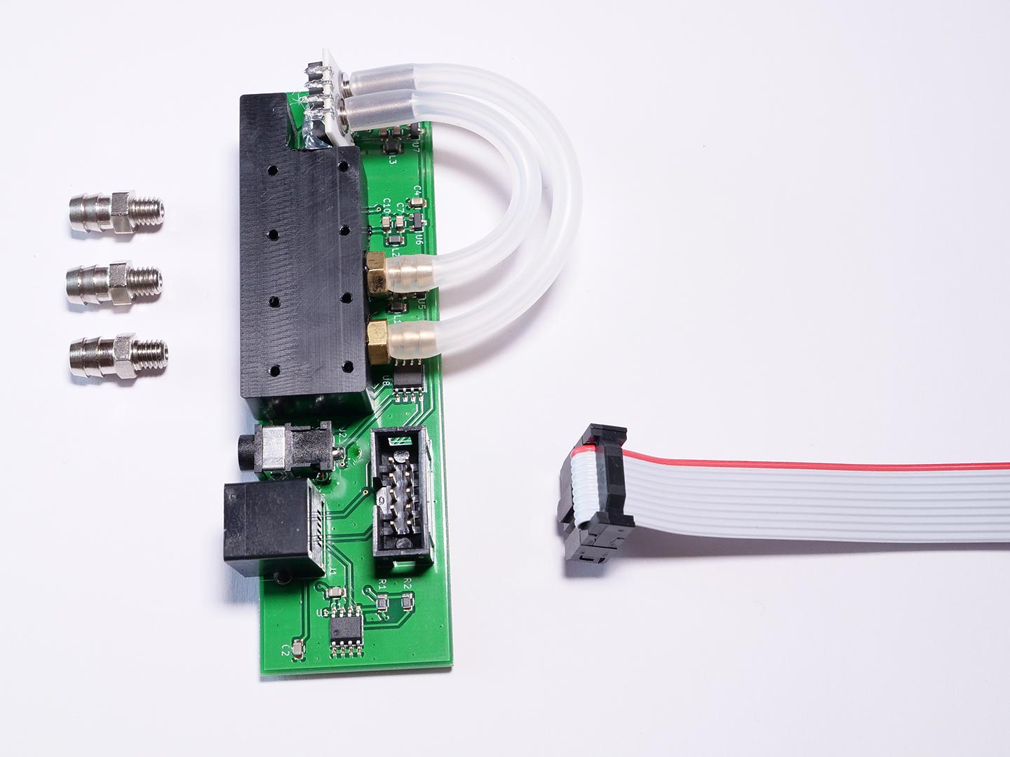
Here's my first pass. It's 73mm across by 52mm deep. The cavity is about 110mm x 60mm. So I can grow the thing a bit. I think rotating J1 90 degrees would give some more space. I think the current board (Stefan's anyway) is about 28mm deep. Caveat: I don't think the DS18B20 connector is properly located, it's close though. Each sensor is on its own regulator. I added a ferrite bead on the inputs to each regulator. The analog supplies are using MMZ1608A252BTD25 with an NCV8163 regulator This has an 800m ohm DC resistance, but considering that the analog supplies are typically running 20mA max, this shouldn't be an issue. The ferrite bead is going to throw some noise in at the low-end because of this, but the NCV8163's have almost 80-90dB of PSRR at low frequency. I anticipate about 35dB@1MHz, 68dB@10MHz, 66dB@100MHz, 32dB@1GHz on the digital (prior to the regulator) Digital is using the same HZ0805D102R-10 with a LDL212PV33R regulator. The board has no audio capability, no 12V regulator and no USB... for now. @iglesiasmarianod @kedder @linuxianer99 Would you guys like to make some comments on what you'd like to see on a new board or what you think of the layout |

|
OK, I know I haven’t been asked, but I thought I’d chime in anyway ;) Regarding the 3.5mm audio jack for the OAT sensor - are we sure about that? Which leads me to the question whether it’s a good idea to have two identical connectors for an OAT sensor and for audio out - I don’t think it is, so I’d probably think about what connector could be used for the OAT sensor instead (2.5mm TRS jack? 4-pin RJ45?) Also, are you sure about the caps in parallel next to the pressure sensors? I’d be worried about potential unintended resonant peaks. Is the intention to use identical cap values? Another thing I see is the ground plane to the right of the ESP32 antenna - are you sure about that? (see https://www.espressif.com/sites/default/files/documentation/esp-wroom-02_pcb_design_and_module_placement_guide_0.pdf) |
|
@DanD222 You are welcome to comment too, I just was hoping to bring some others people into it as well. Timo had suggested a new board driven by an ESP32. Regarding 3.5mm jack/OAT. Part of the problem here is, I have Stefan's OV. I don't know what the difference between Stefan's setup and everyone else's is. On his, the audio is coming out the DB-15, so it'd be impossible to confuse the speaker for the temp sensor unless you were literally not reading any documentation whatsoever. The case of the 3.5mm is plastic, so it can't ground against the OV case. I'm trying to copy the format so I can do a drop in replacement for what I have (with the possible exception that I might need a longer 10 pin cable). Regarding the multiple caps. Any time you have a cap, you are going to have a resonant peak. That's sort of by definition as they all have self-resonance. I'm an IC designer, not a board designer, but it's my understanding that running multiple caps a decade apart is a standard technique. Let's say the SRF of a 1uF cap is 10MHz, and the SRF of a 100nF cap is 100MHz. If the spec calls for a 1uF cap, I can't see how adding a 100nF cap would hurt. On the other hand, I suppose there might be a case made that if the specs calls for a 100nF cap, adding a 1uF cap could hurt, but my gut feeling is it's just not that bad. As for the ground plane. Thanks for pointing out the app note. I'll take that into account. I might also move the regulator to the other side of the ESP32, cut the ground plane a bit short and then run power to the DS2482 under the ESP32. |
|
Hi guys,
My two cents, hope it helps. |
|
|
I pretty much agree with what’s been said by hpmax above. Regarding multiple layouts, I’m not sure if this would be needed actually. Both versions of the sensorboard seem to have the components in roughly the same place, so it would be worthwhile to check this. The audio connector for the standalone board could be where the current OV cinch connector is at the moment, which would be to the left of the I2C connector here: http://www.stefly.aero/wp-content/uploads/2018/03/13_OpenVario2.jpg If doing a Stefly retrofit, one could then simply not populate the audio connector (or drill an extra hole for it in the Stefly case I guess). My idea of a dedicated volume controller for the standalone version kind of goes out of the window in that case.. On the other hand, maybe not - if you can provide pins for a rotary encoder on the PCB, then I can probably interface them to the outside world some other way without compromising backwards-compatibility with existing projects. I’d probably also be OK with having both the OAT sensor and the audio output on 3.5m jacks, in the grand scheme of things. Regarding capacitors in parallel - I’d be worried about what you see in Figure 3 happenning: |
|
I agree with the legal aspects of AHRS. |
|
I quite like the idea of the GPS source being a cheap GPS module rather than an expensive commercial logger - those I would connect to the existing RJ45 sockets on the adapterboard that go through their respective RS232 converters (or wire them to the D-Sub on the Stefly unit). So I’d be perfectly OK with the GPS that connects to the sensorboard being USB or I2C or whatever. “Out-of-the-box”, a bare OpenVario has no GPS source of its own, so why not have the option to connect an inexpensive one to the the sensorboard. |
|
Can someone give me the max dimensions of the standard board? I'll confirm that against the Stefly hardware and then just assume we should make the board as big as possible. I'll try to add a 12V->5V converter and an audio amplifier. We can then design it to select between internal audio and external audio. On the Stefly enclosures it can be unpopulated. On internal it can take audio from Cubieboard and for external, it can take audio from the ESP32. Connector can be another 3.5mm connector. I agree that that's a bit ugly having two 3.5mm connectors. I wasn't planning to add an I2C connector because it just ate board space, but perhaps I could add it. I'm thinking we talk between OV and sensorboard with SPI. All talking on the board is I2C. In terms of GPS, I'm highly inclined to just use USB. USB GPS's are cheap and plentiful and new and better ones keep coming out. I have no real interest in forcing people to buy an expensive proprietary logger. |
|
Also, will look into the compliance article more. However, their self resonant frequency seems off by an order of magnitude. Which means their potential resonance they're worried about could be several hundred MHz on real life. Perhaps that could still be stimulated by a harmonic of a clock. |
|
I’m measuring 30mm x 10mm on the standard sensorboard; you could probably scale the drawings in the Pressure-sensor.pdf from the openvario website to this to get the locations of the parts. Let me know if you want me to do that, of if you need more measurements. There is an I2C connector on the Stefly kit, see here: http://www.stefly.aero/wp-content/uploads/2018/03/13_OpenVario2.jpg You could probably just about fit a vertical USB-A connector into the cutout instead of the 6-pin connector if you decide that’s the way to go. Please check the comms between the OV and sensorboard - I’m pretty sure it’s all I2C. SPI is brought out to the UEXT connector on the sensorboard, but doesn’t go anywhere from there. The schematic's in the link "Schematics and Gerber Files Sensorboard" located here: https://www.openvario.org/doku.php?id=downloads Not sure how much fussing about the two parallel caps is worth.. you could probably investigate on a real board and just not populate one of the caps if it turns out to be a problem. My original line of thinking was that one cap next to the regulator, one cap next to the pressure sensor and the PCB trace between them as the inductance would probably do. |
|
I'm not against USB or cheap GPS. I like racing a lot. I think OpenVario is mainly used for XC and competition soaring. Regarding comms. It is all i2c, we will need to move the ADC voltage sensor to sensorboard. |
|
@iglesiasmarianod Yes, but why connect IGC loggers to the sensorboard, when you can already connect them to the rest of the OpenVario..? If I understand hpmax correctly, the intention here is not to replace the base OpenVario board or the adapterboard, but only the sensorboard (which will have additional on-board processing for handling the sensors and passing the information to the OpenVario base board). So the logger connected to your OpenVario unit will remain connected the same way as it is now, no doors closed. |
|
I was thinking to use only one GPS source. |
|
Sorry Guys, English is not my native language so I may be missunderstanding. I understood @hpmax is proposing to feed sensorboard with it's own gps and then feed openvario with preprocessed data. |
|
The main issue I see is board space / panel space - where would you connect the IGC logger, and would the board be backwards-compatible with existing OV units without adjustments to the case? There’s a 6-pin connector on the sensorboard currently used for I2C; if you wanted to replace it with an IGC-compatible connector, it’d be better to use an 8-pin connector. To be able to use that in an existing Stefly or “classic” OV unit, you’d need to enlarge the hole for it in the case - I'm not sure many people would want to do that. You could probably turn the 6-pin connector into an IGC socket, but I’m not sure that’s a good idea. Regarding your summary - yes, that’s how I understand it. You could in theory have OV feed the sensoarboard with GPS data, but - If you wanted to use the new sensoarboard as a stand-alone unit like I do, you probably wouldn’t connect your logger to it, as you’d want to declare to it. I have a dedicated Bluetooth module for that, and declaring to a logger is also not something I’d expect the new sensorboard to do. So in my eyes connecting a logger to the sensorboard makes things more complicated than they need to be (I don’t mind having two GPS sources actually), and potentially closes the door on a cheap GPS source. It just seems like a lot of extra effort in order to avoid having two GPS sources really. |
|
I feel that sacrificing OpenVario in favor of a stand alone sensorboard is a big nono. This is what we have today.
We have I2C connection to sensorboard and an I2C ADC soldered to mainboard. |

|
I don’t want it to be a sacrifice, I’d like it to be an addition to. I see that there’s a proposal to utilise an ESP32 on a new version of the Sensorboard for connecting to the Mainboard over the current IDC cable, however that may be. I also see that this ESP32 would have Bluetooth or Wifi capability, so I would like this feature to be utilised to send fused sensor data to the outside world. I also see that there’s not all that much room on the OpenVario case, so my concern is about utilising the existing cutouts without making users make new holes in their cases. That’s about it. |
|
Just to be clear... This whole thing came about because I discovered the MS5611 is sensitive to timing and we were getting glitches out of it. Timo proposed using an ESP32 to directly interact with the sensors relieving us of the non-real-time nature of Linux. I'm not actually clear it's the best solution but it is fairly economical and it has plenty of processing power to do a far more advanced Kalman filter. In the meantime, I'm proposing changing all the sensors: MS5611->LP22HH, AMS5915 -> MS4515DO, MPU9150 ->LSM6DSM +MMC5983MA plus switching to better regulators and a better filter topology. I'm not expecting a huge improvement in the pressure sensors, but I'm hoping for some improvement, and the removal of glitches. I am expecting a huge improvement in the other MEMS sensors. I'm also hoping for a far more advanced filtering scheme. Here's the deal:
I'm not interested in putting in RJ45. It's large, its expensive and my guess its probably not as good as a $10 USB GPS from AliExpress. If I can add enough hardware to make it function external to the OV, I'm happy to do that. I would however point out that I'm volunteering to do this and so far, no one's offered to help. So I'm all for trying to make it better, but I'm not real interested in having this overdesigned or putting in a bunch of features I personally don't want. Some questions:
|
|
@hpmax I understand it's volunteer work and thank your efforts. |
|
thanks a lot for helping!! |
|
Hi DanD, I get the quotation for the PCB. It is 20 times more expansive then comparable PCBs. The reason are 0.2mm drills. Is there any reason not change them to 0.3mm? |
|
Hi Dirk, OK, that wasn't intentional. I've enlarged the via hole sizes, see if that helped. |
|
Wow, thanks a lot! Now I only have to pay a twentieth!! |
|
Hello, Are you using this thread as the main communication tool or do you share information in other places as well? |
|
@jlder Much of the conversation has been on this thread, but some has been on emails between me and @DanD222. He has completed a prototype board layout that is designed as a drop in replacement (from a hardware perspective) for the current sensorboard. Only downside is it loses the external I2C interface and is somewhat larger than the original board although it should still work with the original chassis. There is going to be a lot of work required on the software front and the most difficult of it will be sensor fusion so we'd certainly welcome any help you can provide. |
|
@jlder I ordered a couple sensor boards they are completely assembled exept the differential pressure sensor. But I modified the board a bit, so it is now compatible to the OpenVario DS2, too.
I have one board left and I think they will arrive end of March. But to be fair, I have to say that I can't guaranty, that there are no mistakes. Thats why I sell them at cost price! One board costs 67 Euros including shipping to Germany and custom. If you are interested, write me a message. |
|
@hpmax, thanks for the info. |
|
@Blaubart, great to hear your prototype is progressing. |
|
|
|
@Blaubart, can I email you at [email protected] ? |
|
yes |
|
@jlder Hi and welcome. I like your plan with the display, at the moment you’ll need to solder wires to the ESP32 unfortunately. I’ve bumped up the non-DS files to version 19 files in my repo - I've added a 6 pin header for SPI, 5V and GND. I've also been thinking about adding two extra pins for I2C, but, we can use the pads of one of the unused differential pressure sensor for this. So it should be possible to run SPI, I2C and power to an 8pin RJ45 socket for example in order to interface to the outside world, if one figures out how to mount the extra RJ45 socket to the case. |
|
Wow, it's been a while... My hardware doesn't seem to work (I think it was an assembly issue on my end) and I haven't messed with it in a while, but @Blaubart's sent me a copy of his DS2 board and it does work. I just started working on the software. I'm planning to ignore the ESP32 for now and just run it directly through the CubieBoard using the bypass mode, but I do intend to get the ESP32 working after that (I'd like to migrate to the ESP32-S3 also, as it's got a lot of improvements over the S2, still not quite out yet though). I've written code to talk to the Amphenol differential pressure sensor (which I haven't tested), as well as code to talk to the LPS22HH. So far, I'm really happy with the LPS22HH compared to the MS5611. I set it for 75Hz sampling with the ODR/20 low-noise filter using continuous streaming/FIFO buffer. I was able to detect the sampling speed by constantly polling the FIFO to see if there is a new slot in it and recording the last time before a sample is detected and the first time after a sample is detected. Most of the time, there isn't much jitter, but sometimes there is substantial jitter on the sampling rate. This could be a real problem since time between samples will DIRECTLY scale the climb/sink rate. The good news: it's possible it's not real. Given the previous timing issues we've seen on the CB this isn't shocking. I deliberately recorded the time between pollings, and the high jitter samples were well correlated to large deltas on polling time. Looking over a longer time period it appears the sampling rate is about 2% faster than advertised. The good news is, this is pretty easy to compensate for. Looking at the recorded pressure and temperature data sitting on the bench, it looked really good... There was approximately 280 mPa discrepancy between the two sensors (judging from previous data I published this is a substantial improvement over the MS5611). Over 22 minutes of sampling, the discrepancy nearly linearly decreased to 270 mPa. Looking at the difference between the two sensors, we see: Min: 233 mPa, Max: 319 mPa, std dev: 10.1 mPa, mean: 276 mPa (ST advertises a typical absolute error of +/- 500mPa --- so this is pretty close to the "expected" error). Since there was a decreasing discrepancy over time, I decided to compare the difference to the moving average (+/- 15 samples around it): Min: -33 mPa, Max: 34 mPa, std dev: 7.7 mPa Looking at the individual sensors (after comparing to the moving average), I get: One sensor is clearly better than the other. Unfortunately, utilizing that isn't trivial since you can't simply swap the TE and static plumbing since the static is plumbed into the differential sensor too... Visually, the distribution looked very Gaussian with absolutely no glitches or weird behavior. Similarly, temperature had a std deviation of 3.8 mK, with a worst case of +/- 35 mK. Temperature distribution didn't look as good, as there appeared to be multiple spikes in the distribution, but no large outliers. It's worth noting that this MAY be a resolution issue since the resolution of the sensor is only 10mK. The two sensors showed a discrepancy of about 358 mK which may have been changing slightly over time. Either way, I don't think temperature is an issue. Since we're using the integrated filter, it's hard for me to correlate this to a real world comparison of the MS5611 (minus all of the MS5611's bad behavior) and it's probably worth performing similar tests without the filter, and with different sampling rates. Once I can determine the ideal settings, I'm inclined to update sensord just to talk to the LPS22HHs directly, that way @Blaubart et al can start using this thing sooner rather than later. Unfortunately, I can't do real world testing on his board since our POM blocks are different. I tried a simple FIR filter: Y[i]=X[i].5 + X[i-1].5, followed by Y[i]=X[i].25 + X[i-1].25 + X[i-2].25 + X[i-3].25, and then Y[i]=.125X[i]... and then Y[i]=.0625X[i]..., here's what I got in terms of std deviation: Sensor1: 5.5439 mPa: Sensor2: 5.3184 mPa (baseline) Clearly, the noise is NOT white (looking at an FFT confirms this), but again, that's to be expected because it was already filtered. So my immediate plan is to take more data in different configurations and confirm which is best. One realistic question is... Does the built-in filtering actually buy anything? If we're planning to run a filter on the data anyway, could a more sophisticated filter just be constructed. The next stage will be modify sensord to support the LPS22HH. I'm undecided as to whether to make this an updated version of the current software, or to pull the MS5611 support out. I should be able to auto-detect the presence of the LPS22HH, but there's so much crap that is in there because of the MS5611 it'd be nice to just get rid of it. The LPS22HH appears to just work, and so it should be drastically simpler as long as the FIFO buffer doesn't overflow (which take a timing glitch of over 1.2 seconds). |
|
All data is from a bit under 100k data points at each point. Unfiltered: Filtered: My conclusions from this is the best choice is 75Hz. Here's comparison of magnitude of the FFT of 75Hz filtered vs unfiltered. Woopsie... My bad... What I described as mPa in both this and the previous post, is actually 1/10ths of a Pascal (or alternately 100s of mPa). Looking at the data, re-reading my code, and re-reading the datasheet... All of these were taken in "low-noise" mode, which ceases to be an option at 100Hz. So, in fact this is why the noise gets worse at 100Hz. I was thinking the "low-noise" option was being set when I turned the filter on, but it's two totally independent things. I guess the real question is do we use the in-built filter or can we construct a better filter external to the device. It looks like noise is worse on the LPS22HH than the MS5611, but the effective sample rate is almost twice what we were getting out of the MS5611 -- averaging the data gives about 10% better noise than the MS5611 at about 6% lower sample rate. |

|
I initially thought that the unfiltered noise coming out of the sensor was white. I don't think so any more, I think there are peaks every 6000 samples, or roughly 2.4-2.5Hz. It's possible this is a result of the LPF0 filter that is permanently installed. The "fundamental" of this noise is CLEARLY higher than the harmonics. I tried experiments with putting in a Chebyshev Type 1 filter, and it does a great job of knocking out all the high frequency noise... far better than their ODR/20 filter does... But after the ODR/20 filter, a lot of noise content is still in the fundamental, which they clearly knock down somewhat over the unfiltered noise. A survey of various vario manuals, seems to indicate most manufacturers have time constants in the 1-4 second range. I mean, other than adjusting the time constant to match that does anyone have any idea on getting noise out without messing with the actual data? |
|
I have a new version of sensord which appears to work fine with the new board. Anyone who has the new board (either of @DanD222 style or the DS2 style) and wants to try it out, please let me know. This should have all the functionality of the original (if you are using the AMS5915 -- if you're using the Tyco or Amphenol parts, let me know, and I'll work with you to get them working). I'm still working on developing a better filter though. |
|
Now, with a little support, I have connected my sensorboard_Newhardware to an OpenVario with an adapter board DS v1. There is probably a magnetic sensor hidden behind the addresses not listed I have to try this again. In any case, the calibration tool gave me the error message that it couldn't find an eeprom. |
|
Glad you've joined the party! It's difficult for me to answer since things got kinda jumbled and not everyone used the same hardware. Revision control becomes a nightmare. It's supposed to have two LPS22HH (not HB) . It supports several different pitot sensors as well as LSM6DSM (accel/gyro) and MMC5983MA (magnetometer) but it's hard to know what you are using. As you can imagine the march of progress continues, there are newer and better sensors: LPS22DF (I think), and LSM6DSR (there is another sensor now available that Kris claimed has substantially better gyro performance). At this point software development hasn't kept up. I want to get a nice IMU/Kalman engine going on before switching to a better hardware. |
|
Regarding the LSM6DS* IMUs. I've seen this "step function" with LSM6DS3 and have not verified it with other members of the LSM6DS family. However, I got no reaction from ST on this bug report. I wasn't expecting this IMU to support anything fancy, like an artificial horizon. I was just looking for G-load (which XCSoar can use) or a simple slip/turn indicator. But with this "step behavior" I consider this sensor entirely useless. I'm currently using a BMI160 which is good enough for simple applications but also not good enough (too much offset drift) for an artificial horizon (which I'm not even interested in). One more point and I'd like to get your comments on it. I want to implement a protocol to provide XCSoar with data from an IMU. A preliminary proposal is here: |
|
@bomilkar I can try to investigate the problem you cite, but I don't think I saw that. I believe the LSM6DSM is considerably different from the LSM6DS3. There's also the newer LSM6DSR and LSM6DSV. The LSM6DSV has MUCH better gyro performance vs prior models. Kris had been recommending the LSM6DSM, and is now recommending the ICM-42688... However, the LSM6DSV performance is comparable to thepublished ICM42688. I think before you condemn the LSM6DSM/R/V based on the LSM6DS3 we should check it. Do you want me to try to take continuous readings while heating it with a heat gun and look for plots similar to what you showed? As for your proposal... One question that I realistically have is how does XCSoar deal with contradicatory information. For example, if you have two GPS sources putting data in and they show a difference of 20 meters. Is one believed over the other? Are they both believed? Is it an average (weighted or unweighted?) I can see potential issue with this. I'd like to see quite a few things added to the protocol, which would include control position (elevator, aileron, rudder, flaps, air brakes, wheel brakes, gear). These could be a -1 to 1 real value. Gear and wheel brake would presumably be 0 or 1, and air brakes would be 0 to 1. I would propose it be something like: Similarly, I think if you want to extend with IMU data it should be: In the case of the IMU things are a bit more complicated because there's a question of whether or not these are calibrated values. Magnetometers are subject to hard and soft iron offsets. Is the reported number compensated for that? Is it compensated for magnetic variation? Is there compensation being misaligned with the aircrafts axes? It would also be nice to be able to communicate: mute and volume, and to do so fairly bi-directionally. |
|
in our project we found the sensor with the lowest noise and best vertical resolution by far is the Infineon DPS368 |
The Infineon DPS368 is a pressure sensor. This isn't the issue here. I was referring to IMUs. |
|
you are probably right, the LSM6DSM/R/V don't suffer from that issue. But I strongly recommend to test it thoroughly! Yes please "take continuous readings while heating it". I don't have LSM6DSM/R/V. I'm reluctant to define a protocol to transport data which XCSoar can't use. What's the point? So what information do you have, which XCSoar can make use of (now or in the near future)? In my opinion, calibration, compensation, or that kind of calculation should happen near the sensor, not at the consumer side of the data. The consumer (XCSoar in our case) should receive data in "normal" physical (metric) units. I'm proposing acceleration values in units of m/s² . As far as I understand, XCSoar prioritizes the information according to the list of devices. For instance, if (an active) Device A in the list provides valid IAS data, all IAS data from Devices further down in the list (B, C, ...) will be ignored. So, if you have a good GPS source, make sure it is listed before your FLARM. And if your "good GPS" fails for a while XCSoar will fall back to your FLARM. |
From what I see, vertical resolution is irrelevant, the only thing that matters is noise within the bandwidth of concern (which is probably a few Hz, I suppose if you're being anal, maybe 10Hz). It's important to remember that what we care about is accuracy of the first derivative not the original data. I looked through the datasheeet and saw no characterization of noise. If this were truly low noise why wouldn't they be screaming that in the datasheet? There competitors certainly do... Also as @bomilkar points out, we are talking about the IMU not the pressure sensor. |
To be clear, my only setup is a LSM6DSM. After looking at the datasheets again, I think the ICM42688 is actually probably considerably superior to the LSM6 and it's not just noise, it's also gyro drift. I would love to have compensation done at the source rather than at the OV, however, I will point out that in some cases, it's impossible to do compensation without user input. Two obvious examples of this:
This likely will require a somewhat sophisticated interface. If it's the sensorboard... guess what, you're only interface is through OV, whether it's a separate software package that's loaded through ovmenu, or something built into xcsoar. Your choices aren't that broad. As for why include data XCSoar isn't going to use. What you mean is, XCSoar isn't using it right now. Why not? Because it has no way to get the information. Sort of a chicken and the egg problem. But someone may decide to use it if it were available... And the thing is... there's really very little cost to create the protocol. XCSoar presumably ignores NMEA sentences it doesn't understand, so you could define the protocol, and XCSoar could simply ignore it until it supports it. In my case, I wanted to do a full IMU, because I was hoping it would help improve the vario performance. Perhaps I'm kidding myself. In that case, I want the ability to transfer IMU data (magnetic heading, pitch, roll, yaw, slip/skid info, air speed, ground vector, lat/lon/altitude, G's, etc). Some/most of this information is already available (and supported) in the Levil protocol. |
If compensation cannot be done in the sensor itself, it should be done in OV. Not in XCSoar. That's what I meant. |
Yea, the ICM42688 IMU looks great .... on paper. However, I don't know what would be acceptable (for drift and noise) in order to still be useful to build a IMU-based variometer. A LSM6DS3 and a BMI160 is not at all sufficient, I think. And don't forget: what about availability? Where can you buy this thing in low quantities? BTW: your comment about the pressure sensor. I fully agree, modern pressure sensors' performance in terms of accuracy and noise are much better than what we need. Don't forget our pressure ports are much much worse, So a vertical resolution of 0.5 m is about 10x better than what your TE, Stat, Pitot ports deliver. |
I've noticed the appearance of Android-based OV-like devices running XCSoar, so that's also something to consider, especially if the New Hardware is to be used as a stand-alone sensor box. |
|
@bomilkar I'm American so in terms of availability, I'll say that both Digikey and Mouser have over 10k units of the ICM42688 in stock, and they are available in qty 1. At this point in time, I see no reason to consider availability as a problem. Is it good enough? Again, I got the suggestion from Kris Winer... he claimed he was able to get drift down to 6 degrees per hour. I think that was uncorrected drift, but I could be wrong. In this case he stated he was driving the ICM with an external clock, from a ST uC and claimed: "The STM32L4 is capable of outputting a 32.768 kHz square wave from its 1-ppm-accuracy RTC embedded clock." Flat out, that sounds absurd to me. 1ppm is expensive and no dirt cheap micro is going to have a built in 32kHz oscillator that's 1ppm. It's possible that the 32kHz output is derived from a crystal oscillator and within 1 ppm of the derived clock noise. However, that said, I was able to find a SiT1566 that was 3ppm for $4, and there's a variant closer to $1 which is 5ppm. They're both TCXO, and I'm confident it's substantially less jittery more accurate than what Kris used. Is 6 degrees per hour too much? My guess is... no, remember you have a magnetometer which when properly calibrated should give you the correct angle (which is the integral of the output of the gyro). So how hard should it be to mostly null out long term drift as long it's small. But I'm not an expert. Regarding pressure sensors... Modern sensors have more than adequate resolution and accuracy for what we need, but noise... Noise is problematic. It's hard to emphasize how little of a pressure change is needed to really screw you up. The problem is that noise is effectively multiplied by the inverse of the sample period. Half the sample period, double the noise... And that's just the noise because of the derivative term. The sensor itself probably has noise that increases by 41% because you doubled the bandwidth. A fast responding sensor is VERY vulnerable. This brings up the other source of noise you mentioned. Jitter in the clock. The LPS22 series have an internal oscillator. This is way better than relying on a non-real time system like the original sensorboard... but i don't know the characteristics of the LPS22 clock. There is likely to be some error, perhaps 1% or so which should translate to the same percentage error in the derivative. A 1% error is probably tolerable, but it's also easily corrected. Just pipe the 32kHz oscillator into a counter on the uC, and count how many samples you get per 32k clock ticks. But what about jitter in the LPS22 oscillator. There's no spec I saw on that. If it's high frequency jitter, no problem, it gets filtered. If it's low frequency... in or near your passband, you're going to have a bad day. It may be you could run it off a divided down clock from the SiT1566. Looking at the datasheet, it looks like worst case jitter is on the order of 0.1% from one period to the next, but typical is closer to 0.01%. To make things a bit more confusing. that's noise characterized from 100Hz to the Nyquist rate. Which is basically WAY more thermal noise than we are likely exposed to, but way less flicker noise. So... who knows what the real values are. I'd love to spin a new board that uses the LPS22DF, the SiT1566 and the ICM42688 -- it could be a major step up. BUT... I've done the low hanging fruit. I wrote software to read the LPS22HH, and LSM6DSM... but I don't have the software in place to use it, and without that, what's the point. Other upgrades would be to switch to ESP32S3 which has Bluetooth and a second core, and switching to a better (cleaner) power converter. Those two upgrades would make using this as an external board (outside the OV) far more desireable and make more sense of removing the custom electronics package from the computer/display/interface which theoretically could be more generic. |
I figured I'd start a new comment to discuss the second gen sensorboard. My proposed hardware at this point is:
LPS22HH (replaces MS5611). I really don't know which is better, but the LPS22HH is a LOT cheaper, and may actually be superior. It's worth testing.
MS4515DO (replaces AMS5915). Again, I don't know if its better, specs are slightly better, it's a little cheaper, and more available (at least in the United States). It's worth testing.
NCV8163 (NCP163 also seems to be a pretty equivalent part, replaces MCP1700) Slightly more expensive, and higher quiescent current (but still trivial compared to its load), it's smaller and spec-wise blows the doors off the MCP1700. Electrical noise is reduced by at least 30dB both in terms of PSRR and output noise. This is a DRAMATIC improvement. An open question on this is how many do we want? One for each sensor? Using independent regulators both improves PSRR and decreases cross talk noise on the supply.
ESP32-WROOM-32E Timo suggested it, I'm willing to go with it. I am a bit concerned about how much power it can consume, but I presume it's only consuming massive amounts of power when it's doing something useful.
LDL212PV33R... regulator for the ESP32. An NCV8613 could probably do the job, but they have a 250mA max, and aren't real good about dissipating power -- and the documentation I've seen on the ESP32 says you want a 500mA power supply. For manufacturing and cost reasons, it would be nice to stick with all one type, but oh well...
DS2482 (carried over)
LSM6DSM and MMC5983MA (replaces the MPU9150) The 9150 is long obsolete, the 9250 that replaced it is obsolete too. I spoke to Kris Winer who has a lot of experience testing different parts. Those were his recommendations along with the LPS22HH
Some additional comments/thoughts:
Is there supposed to be an audio amp on the sensorboard? The one I got from Stefan has the amplifier on the adapterboard. Regardless, I'd be inclined to replace the AS1701. Stefan is using the MAX9718A which seems to be a reasonable choice. The MAX98304 is a really nice Class D amplifier. Downsides are that you can't get more than 12dB gain out of it, and that its Class D and hence may emit noise. I'm building up an amplifier board now based on the MAX98304 and I think I can knock the EMI down by at least 60dB over all the frequencies I'd care about (IF, RX+/-IF freq) over already good results, and the 98304 is quiet to begin with by Class D standards. So I'm hoping it'll be okay. Otherwise, the MAX9718A is a decent choice, but it does have heat dissipation issues.
Do we want a drop-in replacement for the current board, or should this be an external unit which could interface to other things (for example a direct vario display) -- if so, how do we interface to the OV? One other possible choice here is the ESP32-S2, which is allegedly cheaper and lower power and supports USB. Downside is you also lose a core, and some memory, and Bluetooth. But allegedly the newer process is faster at floating point, which is what this thing is going to spend most of it's time doing. I like the notion of this being an external device that could directly receive GPS input, and directly drive an external display and then provide the OV with a complete IMU interface.
The new board is almost certainly going to be larger. The main driver for that is the ESP32, but there's just going to be more stuff on it period. I think there's plenty of room in the case, but I do worry because I think it's only held in place by the fitting screwed into the POM block. I don't know if this will cause a moment issue if the board extends further away from the end of the case.
Does anyone have a files with the board layout? I'd like to keep the sensor components in the same relative location so that the POM block can be reused.
EEPROM? I'm not sure what the point is. I'm not even sure what the point is in the current version. The data could just be stored in the configuration file (and in fact, it already is, so the EEPROM is just another compensation on top of the pre-existing compensation).
Anyone have any thoughts about putting components (capacitors in particular) on the bottom of the board? I want to be able to bypass the sensors under the POM block without interfering with the POM block.
The text was updated successfully, but these errors were encountered: