Part two. Continues from "Patching and installing Micromake D1 firmware (Repetier)"
Obtain the OpenDACT utility here - http://forum.seemecnc.com/viewtopic.php?f=36&t=8698 You will need version 3.0.1A. Download the distribution, unzip it into convenient location and execute setup.exe first. Then, run Delta Kinematics Calibration Tool.exe.
OpenDACT has a bug - because it was written by an American, it assumes that the decimal part in integers is separated by the point character. Yet in Russia and few other countries comma is used as decimal separator instead. Once the software meets an unexpected symbol, it crashes. Author has been notified about this bug - coelacant1/OpenDACT#13 - but unless fixed, it can be circumvented by changing "locale settings" in Windows. Apply this fix if you are affected by this bug:
Save your current settings to a file or write them down in case you'd want to have them back. I strongly suggest resetting all values to defaults so OpenDACT will be starting from scratch.
Launch CURA and connect to printer. In the menu, choose Machine -> Firmware configuration. You'll get this window:
Take a sheet of paper and write down old values before you change them to defaults - you'll need these in case you want everything back.
You will have to enter these defaults::
| Setting | What it does | default value |
|---|---|---|
| Z max length [mm] | Sets the correct distance from top to bed | Leave as is |
| Tower X endstop offset [steps] | Adjusts height of 1st tower | 0 |
| Tower Y endstop offset [steps] | Adjusts height of 2nd tower | 0 |
| Tower Z endstop offset [steps] | Adjusts height of 3rd tower | 0 |
| Diagonal rod length [mm] | Sets the length of the diagonals | 217 |
| Horizontal rod radius at 0,0 [mm] | Sets radius of the effector assembly | 94.5 |
| Alpha A(210): | Adjusts the angle of 1st tower (X) | 210 degrees |
| Alpha B(330): | Adjusts the angle of 2nd tower (Y) | 330 degrees |
| Alpha C(90): | Adjusts the angle of 3rd tower (Z) | 90 degrees |
| Delta Radius A(0): | Adjusts the distance of 1st tower from center | 0 |
| Delta Radius B(0): | Adjusts the distance of 1st tower from center | 0 |
| Delta Radius C(0): | Adjusts the distance of 1st tower from center | 0 |
| Corr. diagonal A [mm] | Fixes the tilt of the 1st tower | 0 |
| Corr. diagonal B [mm] | Fixes the tilt of the 2nd tower | 0 |
| Corr. diagonal C [mm] | Fixes the tilt of the 3rd tower | 0 |
| Z-probe height [mm] | Sets the height of Z-sensor | 0 |
These g-codes will change all settings at once - copy the list and execute it using Repetier, Pronterface or whatever tool you like.
M206 T3 P153 X312.000   ; Z max length [mm]
M206 T1 P893 S000       ; Tower X endstop offset [steps]
M206 T1 P895 S000       ; Tower Y endstop offset [steps]
M206 T1 P897 S000       ; Tower Z endstop offset [steps]
M206 T3 P881 X217.000   ; Diagonal rod length [mm]
M206 T3 P885 X95.2      ; Horizontal rod radius at 0,0 [mm]
M206 T3 P901 X210.00    ; Alpha A(210):
M206 T3 P905 X330.00    ; Alpha B(330):
M206 T3 P909 X90.000    ; Alpha C(90):
M206 T3 P913  X0.000    ; Delta Radius A(0):
M206 T3 P917  X0.000    ; Delta Radius B(0):
M206 T3 P921  X0.000    ; Delta Radius C(0):
M206 T3 P933  X0.000    ; Corr. diagonal A [mm]
M206 T3 P937  X0.000    ; Corr. diagonal B [mm]
M206 T3 P941  X0.000    ; Corr. diagonal C [mm]
M206 T3 P808  X0.000    ; Z-probe height [mm]
Please ensure that the "steps per mm" parameter is correctly set - it can be corrupted during firmware upgrade!
If you are using stock Z-probe, skip this section.
If you are using snap-on Z-probe, please ensure that Z-probe height [mm] is set to zero in your printer's EEPROM, and the value of Z max length [mm] is decreased by the probe's height.
For example, my printer's height is 311.82mm. The "teddybear" Z-probe I am using is attached below on a hinge, its height is 12.4mm. I subtracted 12.4 from the original height and got 293.42mm, - I entered this new value into EEPROM as the new Z max length [mm].
(If you like this design of the Z-probe, you can purchase it from Pinshape. It is totally worth the asking price.)
(Please note, screenshots were made with an older version of the program. Version you've downloaded, '3.1.0A', will look slightly different.)
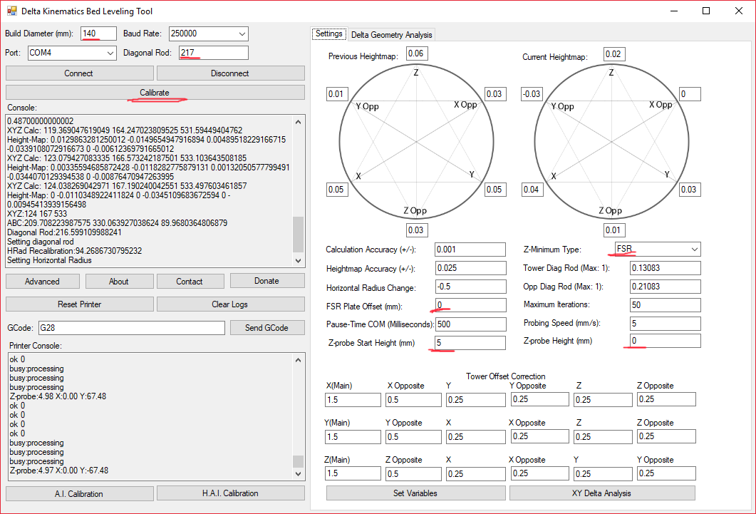
Launch the program. In the Build diameter enter the diameter of the circle you'd like to probe during calibration. Don't be greedy, there is no point in probing the edges of the glass. The design of the delta makes the effector bend on the edges of the plate making the measurements inaccurate. The diameter of 100 - 120mm is perfectly enough!
In Diagonal rod field enter 217. Select the correct port and choose Baud rate of 250 000. Hit Connect.
Then hit Advanced. Ensure that Z-minimum type is set to FSR (and not Z-probe!), and fields FSR plate offset amd Z-probe height are set to zero.
Z-probe start height sets the height starting from which printer moves its effector very slowly. If you set it too high, calibration will proceed slower. Setting it too low creates the risk of full speed collision of the nozzle and the glass. Use your discretion when setting this.
Once you've set the values, hit H.A.I. Calibrate (not A.I. Calibrate) or Calibrate). The rest will be done automatically.
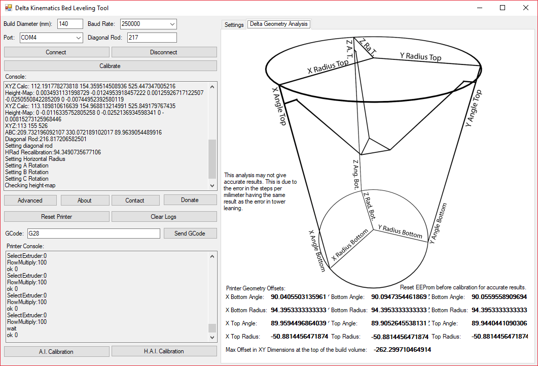
You can see for yourself how flawed your build is by looking at the values on the second tab:
OpenDACT is buggy and glitchy yet it does amazing job. If you are good at coding in C# - please contribute to https://github.com/RollieRowland/OpenDACT - it will be greatly appreciated by the community.
Put a piece of heavy paper on the glass - piece of thick magazine cover page is OK. Use the LCD screen menu, open Configuration -> Z calib. -> Z position.
Carefully, like a bank robber in the Hollywood heist movie, rotate the knob and bring the nozzle down so it holds paper yet you can move it with your fingers back and forth without much effort.
Once you've found the right position, use Set Z=0 menu to store correct height value in EEPROM.


