** Warning! This tutorial has been deprecated - read this 2-part article instead **
This HOWTO was written for Micromake users' group on Facebook.
For a long time I wasn't able to print something with a footprint larger than 5cm in diameter on my Micromake D1. "Auto level" function in CURA never worked for me quite well. This is what I was getting with a test plate model from Thingiverse even with the best 0.04mm tolerance:
And now I've managed to get this quality with layer thickness set to 0.15mm even with full-plate prints:
I was inspired by this video from Repetier project. Unfortunately, it relies on some commands that Micromake D1 doesn't support, so I'll be using just the part that describes measuring offsets of each vertical tower.
You will need:
- something long, like 30cm steel ruler or a piece of 30-40cm metal rod
- calculator (Windows
calc.exeis just fine) - This brilliant online calculator (open it in new tab of your browser)
- 5-10 minutes of time
- any software that can send commands to COM port. I was using Repetier Host, but you can even use Arduino's Serial monitor - just set the correct port speed (250 000 baud) and connect.
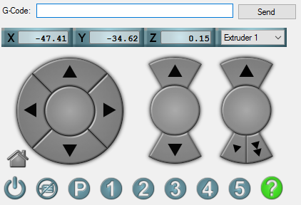
This is where you enter manual commands to your printer in Repetier:
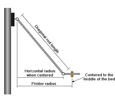
Delta printers have a lot of variables to play with:
...and imperfections with lengths and towers misplaced by even a fraction of a degree can cause a lot of trouble.
Basically, calibration means solving an equation with seven variables:
- three endstop corrections,
- delta radius,
- two tower angular position corrections, and
- diagonal rod length.
It is some serious math.
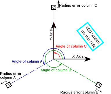
To make things worse, all those variables are poorly named. You might have got used with towers named X, Y and Z. To make things worse, the Cartesian axes in which the print head moves, are also named X, Y and Z. And, for some reason, towers are sometimes named not X, Y and Z, but A, B and C. And to seriously fuck your brain, the angles of tower placement (which are 90, 210 and 330 degrees), are also named A, B, and C. On top of that, some adjustments are measured in millimeters, and some - in motor steps. Don't ask me why.
First, check that the tension of all three belts is satisfactory. Inspect all screws, tighten those that went loose. Inspect all endstops as well. This is important!
If you are printing with ABS, make sure your printer is warmed up and you are conducting the measurements on the hot printer (because metal parts expand and dimensions slightly change). On the LCD screen select Quick settings -> Preheat ABS to do that.
If you are connected to COM port, fire this command:
G28 ; Home
It will tell the printer to home the printing head. Then use these:
M321 ; Deactivates auto level
M322 ; Resets auto level matrix
This will reset the printer completely.
Now let's bring all pulleys to the 20cm height (or, at least, what your printer believes is 20cm height). X0 Y0 parameters of the following command tell the head to stay at the point with the coordinates of 0, 0 and Z200 parameter tells it to stay 200mm from below.
G1 X0 Y0 Z200 ; Move extruder down to 20cm height. Adjust value of "Z" if your rod / ruler won't fit
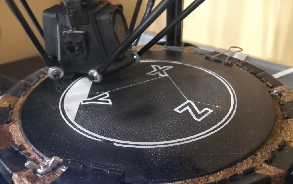
Now comes the tricky part. Look at the schematics above, and relative to the position of the LCD screen, decide which tower is X, which is Y, and which is Z. Put a paper sticker with a letter on each one - it helps.
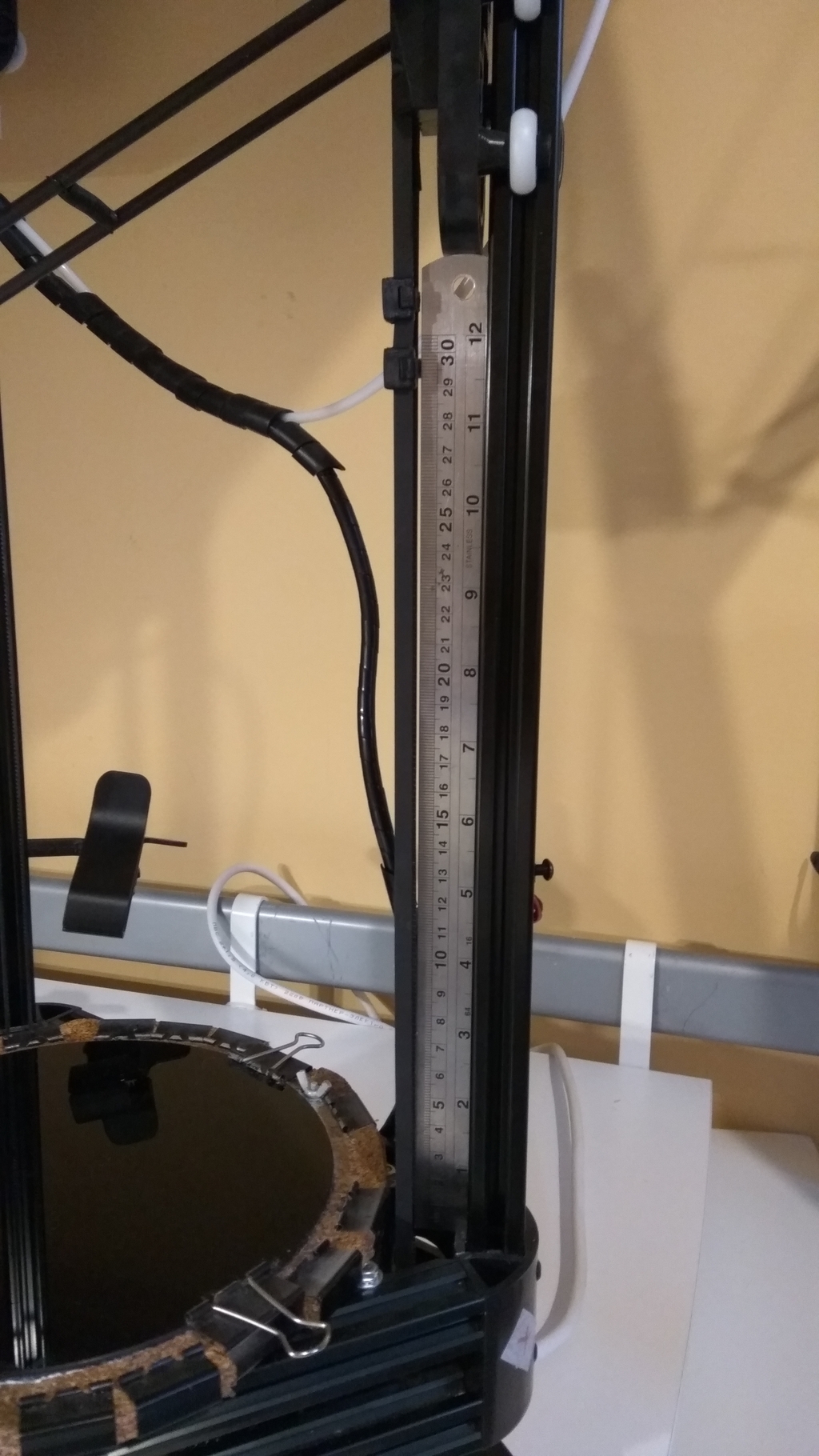
Let's start with X tower. Place a rod firmly into the slot of the aluminum beam (I used steel ruler):
Next, run this command:
M99 X0 ; Disables stepper motor for tower X for 10 seconds.
Stepper motors for towers Y and Z will still work. But motor for tower X will turn off for 10 seconds and allow you to bring the pulley down, so it touches your metal rod (or ruler). Hold it firmly and wait till the stepper "wakes up". Then gently remove the rod.
Repeat the procedure for remaining towers one by one:
M99 Y0 ; Disables stepper motor for tower Y for 10 seconds.
M99 Z0 ; Disables stepper motor for tower Z for 10 seconds.
At this step you don't really need to know the exact length of your rod (or ruler). You just ensured that the distance between each pulley and the bottom is uniform.
Next, run this command:
G132 S1 ; Calculates offsets and stores them in EEPROM.
It will move all pulleys up, until they reach the endstops, and return something like this:
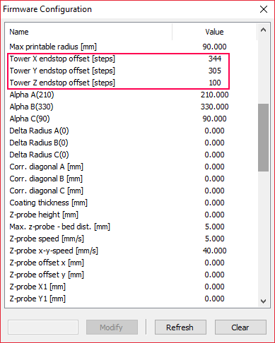
Tower 1:344
Tower 2:305
Tower 3:100
These are exact offsets measured by the printer. Write them down and enter them in the printer's memory ("EEPROM"). To access this dialog in Repetier, press Alt+E. In CURA you can get to that dialog via Use Machine -> Firmware configuration menus.
Send the "home all" command to apply your changes:
G28 ; Home
I also wanted to have the printer's height measured exactly. My printer has had a value of 329.260 Z max length [mm] stored in memory. I added 1cm (10mm) and rounded it up to 340mm and stored the new value in EEPROM. (Use Machine -> Firmware configuration menu to change printer's settings in CURA.)
Run these commands to first home the head and then move it down:
G28 ; Home
G1 X0 Y0 Z20 ; Move extruder down to about 10mm height (20mm actual minus 10mm gap we've added by rounding up the 'Z max length')
The printer will move the print nozzle at what it thinks is 2cm distance from the glass. But since we've messed with the height parameter, the actual distance will be smaller.
On the LCD screen select Configuration -> Z calib. -> Z position. Gently turn the dial counter-clockwise to move the head down. Do it slowly, like a burglar in a bank heist movie. If you rotate the knob too fast, it will crash into the glass at full speed!
If you have still "crash-landed" the nozzle in the glass, causing it to slide sideways, issue the "Home all" command to start over.
G28 ; Home
Multiple advice on the web suggest using "paper test" - you place the piece of thin paper on the glass and move the nozzle down until it holds the paper firmly. I found a better way - it turns out that the sound of the fan on the printing head changes when you firmly touch the glass surface. Attention - you don't need to push down so hard that Z-probe button on the effector clicks; gentle but firm touch is enough.
Write down the Z position number you got on the screen. Get a calculator and substract it from the rounded up Z max length [mm] value you placed into printer's EEPROM memory. This is your printer's correct print height. (If you will get negative number somehow, remember the laws of arithmetics - subtracting negative numbers means adding them.)
Other option is to use the Configuration -> Z calib. -> Set Z=0 menu while the nozzle is touching the glass. Printer will adjust the height itself.
As the result we now know exact values for four of the seven variables needed by calibration formula.
Open the link to online calculator and start filling these values:
| Setting | What to enter |
|---|---|
| Firmware type: | choose Repetier (don't forget this one!) |
| Steps/mm: | enter 100 (or 200 if you enabled 32-microstepping using jumper on the board) |
| Initial endstop corrections: | enter the values for X, Y, Z which we just have measured with the metal rod or ruler |
| Initial diagonal rod length: | if you use standard Micromake rods, enter 217. If you use something custom, measure length from hole to hole in mm. |
| Initial delta radius: | for the dome-shaped Micromake effector (with two fans on the sides) it is 95mm |
| Initial homed height: | it is the height you just calculated. Enter it here. |
| Initial tower angular position corrections: | leave zeroes there. |
| Printable bed radius: | because I have paper clips around my glass, my print area is reduced. So in my case I entered 75mm, but you can try 80mm |
| Number of probe points: | change this to 10 |
| Number of factors to calibrate: | change to 7. If you are 100% certain that your diagonal rods are 217mm in length, but calculator would later give you some clearly wrong values, change this to 6. This will force the calculator to play with other variables, but keep Diagonal rod length intact |
| Normalize endstops: | leave unchecked |
The calculator will suggest you ten points to probe on the print bed and will ask you to fill the distance between the glass and the print nozzle. For example, points like X: 64.95; Y37.50.
I found it boring to move the head to each of those ten points using just LCD screen menu and a dial. I copied the list of suggested coordinates to Windows Notepad and made a list of G-codes:
G28
G1 X0.00	Y75.00 Z20   ; Hover over Point 0
G28
G1 X64.95	Y37.50 Z20   ; Hover over Point 1
G28
G1 X64.95	Y-37.50 Z20   ; Hover over Point 2
G28
G1 X0.00	Y-75.00 Z20   ; Hover over Point 3
G28
G1 X-64.95	Y-37.50 Z20   ; Hover over Point 4
G28
G1 X-64.95	Y37.50 Z20   ; Hover over Point 5
G28
G1 X0.00	Y37.50 Z20   ; Hover over Point 6
G28
G1 X32.48	Y-18.75 Z20   ; Hover over Point 7
G28
G1 X-32.48	Y-18.75 Z20   ; Hover over Point 8
G28
G1 X0	Y0 Z20   ; Hover over Point 9
G28 ; return back home
Have you noticed the Z20 in each of ten coordinates? It made the head to stop 20mm over the glass (at least, printer thought that it was 20mm...) and allowed me to move the head down manually using LCD screen menu, Configuration -> Z calib. -> Z position.
If the nozzle touched the glass plate firmly, but the LCD screen showed me that the distance was still, say, 1.23mm, I entered negative 1.23 value into the form.
If the glass is too far away, the value on LCD screen becomes negative when I finally touch the bed. In that case I enter the positive number in the form. I.e. if the LCD screen reads -1.22, I enter 1.22 into the online form for that point.
If you did everything right, you must have corrective values for each of the ten test points.
Hit Calculate under the form, it will give you the following output, which needs to be saved to appropriate fields in EEPROM memory of the printer. Make sure you enter the values with decimal point, not comma. This is important for Russian users, because Russian version of Windows makes decumal numbers display in the former way - if you blindly will copy&paste the values, you will confuse your printer.
| Value | What to do with it: |
|---|---|
| New endstop corrections | Save X:, Y: and Z: to Tower X endstop offset, Tower Y endstop offset and Tower Z endstop offset, accordingly. If the calculator gives you values with decimal part, round it to nearest value (i.e. if you get 56.9, round it to 57) - the printer's firmware will not accept it otherwise. |
| New diagonal rod length | Save to Diagonal rod length. It is OK if the calculator will suggest you some minor corrections to the initial value of 217mm. If it is wildly off, consider the note about Nuumber of factors to calibrate above |
| New delta radius | Save to Horizontal rod radius at 0,0 |
| New homed height | Save this value in Z max length |
| New tower position angle corrections | This is the trickiest part. You need to either add or substract these values from values stored in Alpha A(210), Alpha B(330) and Alpha C(90). If, for example, the wizard gave you Z: -0.5, it means that you need to substract 0.5 degree form the angle of tower Z (C), which, by default, is 90 degrees. |
| Commands | Ignore whatever the wizard generated there. These codes work with Marlin firmware, ours doesn't understand them. |
You might be surprised that you had to alter the values of Z max length and endstop offsets that you precisely measured before (?!) Actually, it makes sense. If the wizard decides that your towers are not absolutely vertical, it may decide to compensate these imperfections and altering those values will make sense. If you don't want to think about math and trigonometry, just let it go.
Finish it by issuing a command that will turn auto leveling back on:
M320 S2 ; Activates auto level permanently
If you aren't tired and want the perfect results, home the printer, restart it, and repeat this Step 4 once again. I've got an amazing precision after just 2 attempts. On the final step the tool gave me the following estimate:
Success! Calibrated 7 factors using 10 points, deviation before 0.44, after 0.04
Unlike the autolevel in CURA, this "0.04" result means that I am getting this tolerance not just on a given radius, but in each and every point of the platform.
This is an 11cm by 11cm print, with perfect adhesion of the ABS to a simple hair spray surface, with zero curling of the corners - all thanks to a near-perfect leveling of the print head. It doesn't scratch the glass, and extrusion width is perfect in every point.
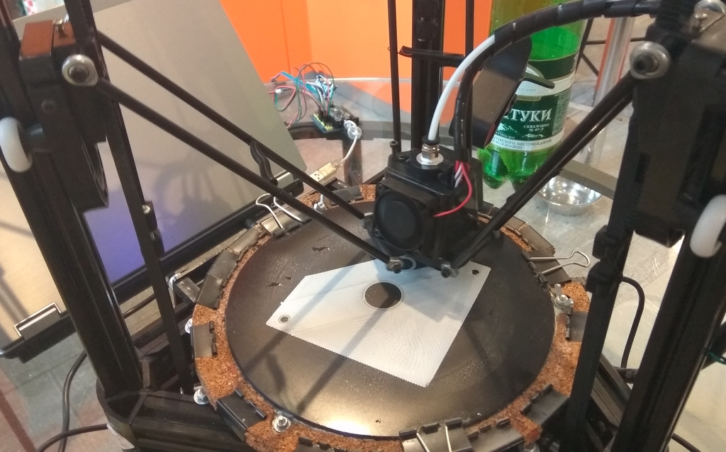
And I am getting this result on the cheapest "pulley" edition of Micromake D1:

