New Build - Possibly H2 #73
Replies: 6 comments 6 replies
-
|
Here's a short video of the encoder to see if it is functional. It turns out I have a 800PPR encoder. |
Beta Was this translation helpful? Give feedback.
-
|
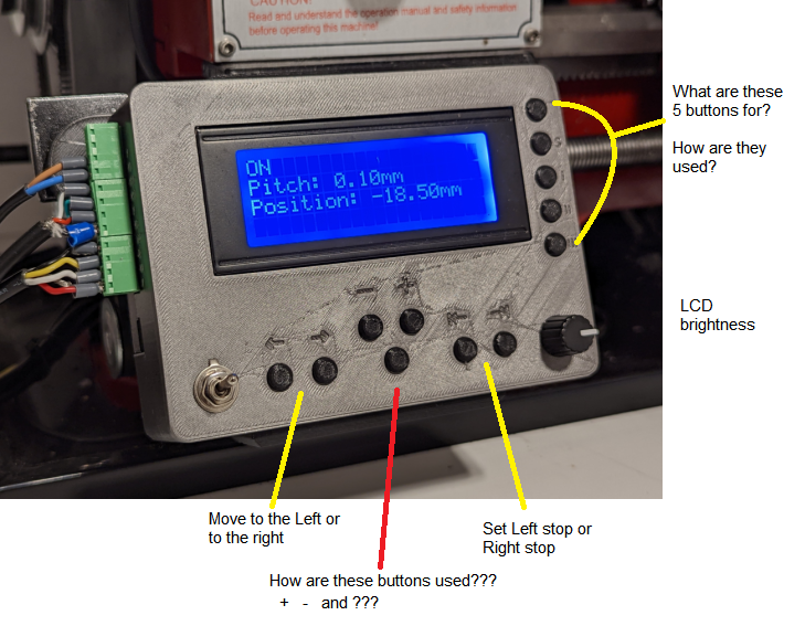
@Lester444 looking great! Please keep us updated on the progress. Here's what H2 buttons do: |
Beta Was this translation helpful? Give feedback.
-
|
Quick update: Most switches have been wired (B0~B6). Issues I am having right now: I do not understand what is wrong. |
Beta Was this translation helpful? Give feedback.
-
|
This is how I wired the switches, all of these switches connect to GND when pressed: |
Beta Was this translation helpful? Give feedback.
-
|
It's running! :) I still need to get comfortable with using this so I'm practicing on wood for now. |
Beta Was this translation helpful? Give feedback.
-
|
Hello Maxim. I thought I would document my learnings in this project and some of the changes I made to the hardware and firmware. Perhaps somebody would find it useful in the future? Stepper Motor: Gear Drive for the leadscrew: My scary moment: AnalogRead (A6): I edited the software so that it no longer uses analogRead(_). Instead, I added switches to NANO pins A0, A1, A2 which are not used anyway. So now I do digitalRead(A0) and it is immune to electrical noise. Thank you very much Maxim, your generosity is greatly appreciated. Warm greetings from the Philippines! (BTW I have my eyes on the MEGA ELS....... :) ) |
Beta Was this translation helpful? Give feedback.


-
Greetings.
First, a big thank you to Maxim for making this project available to everyone. The images and videos were a big help to me while I was trying to figure out how to make one.
I have started my build.
The encoder's gear was not 3D printed but rather cut on a CNC router. Material used is flat Acrylic plastic 4.5mm thick. The gear was then glued onto a hub (Polyester plastic) to hold it on the encoder's shaft.
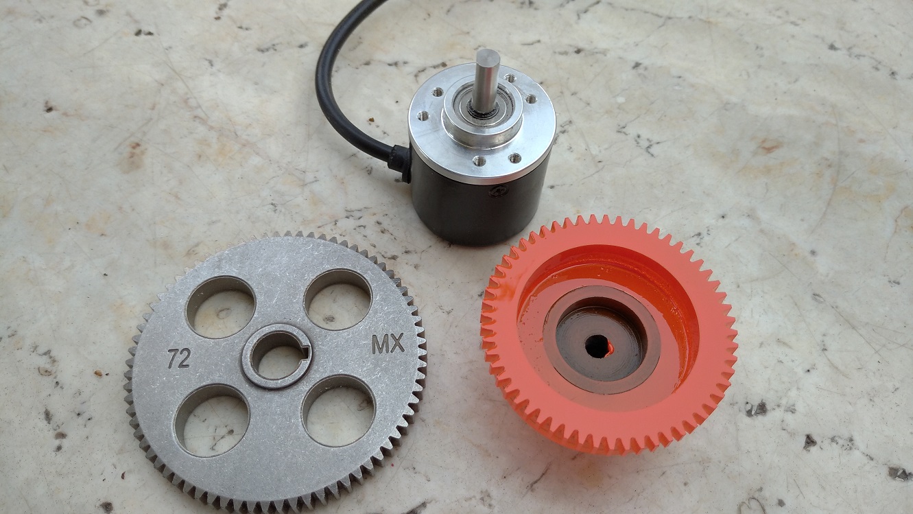
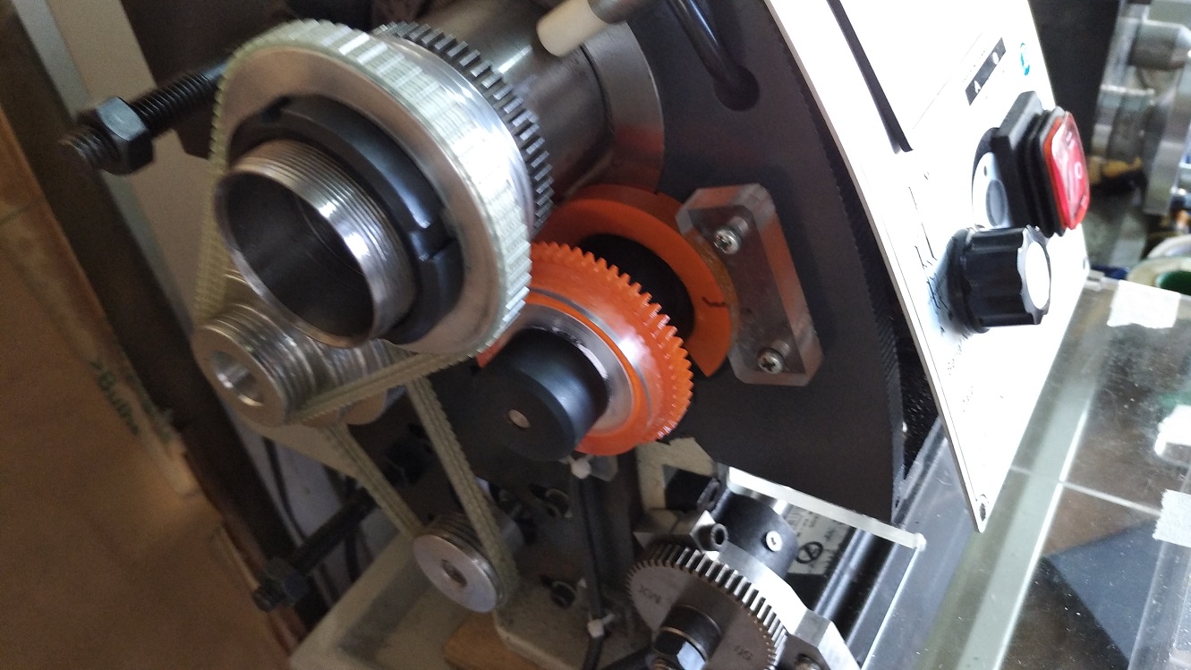
I am using a Servo Stepper motor, NEMA23 size. I was planning on using a belt but got impatient, then I realized I can re-use one original gear from the lathe and the other gear was again CNC cut from 6063-T6 aluminum plate 6.4mm thick. The hub was made on the lathe itself, from 6063-T6 aluminum rod 25mm diameter. The gear and hub were glued together, then a hole was drilled in between the interface of the hub & gear, and 3mm pin was glued into this hole. The pin acts like a shear key but this one can't be replaced.
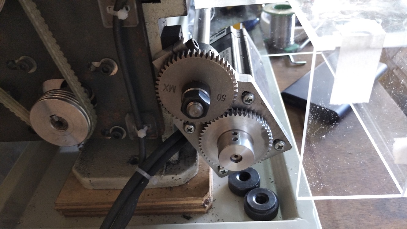
The motor mount was cut from 10.5mm-thick aluminum plate.
I plan to use a different layout for the buttons & display but that's just a personal preference. An Acrylic pastic housing is already made but I have not yet drilled holes for the buttons and switches, because some of the switches I do not yet understand how they are used.
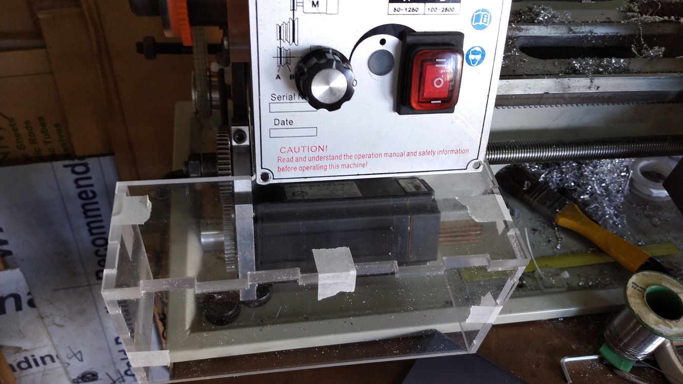
These buttons I do not understand how to use:
Beta Was this translation helpful? Give feedback.
All reactions