AmiiboLink / AmiLoop #7574
Replies: 1 comment
-
|
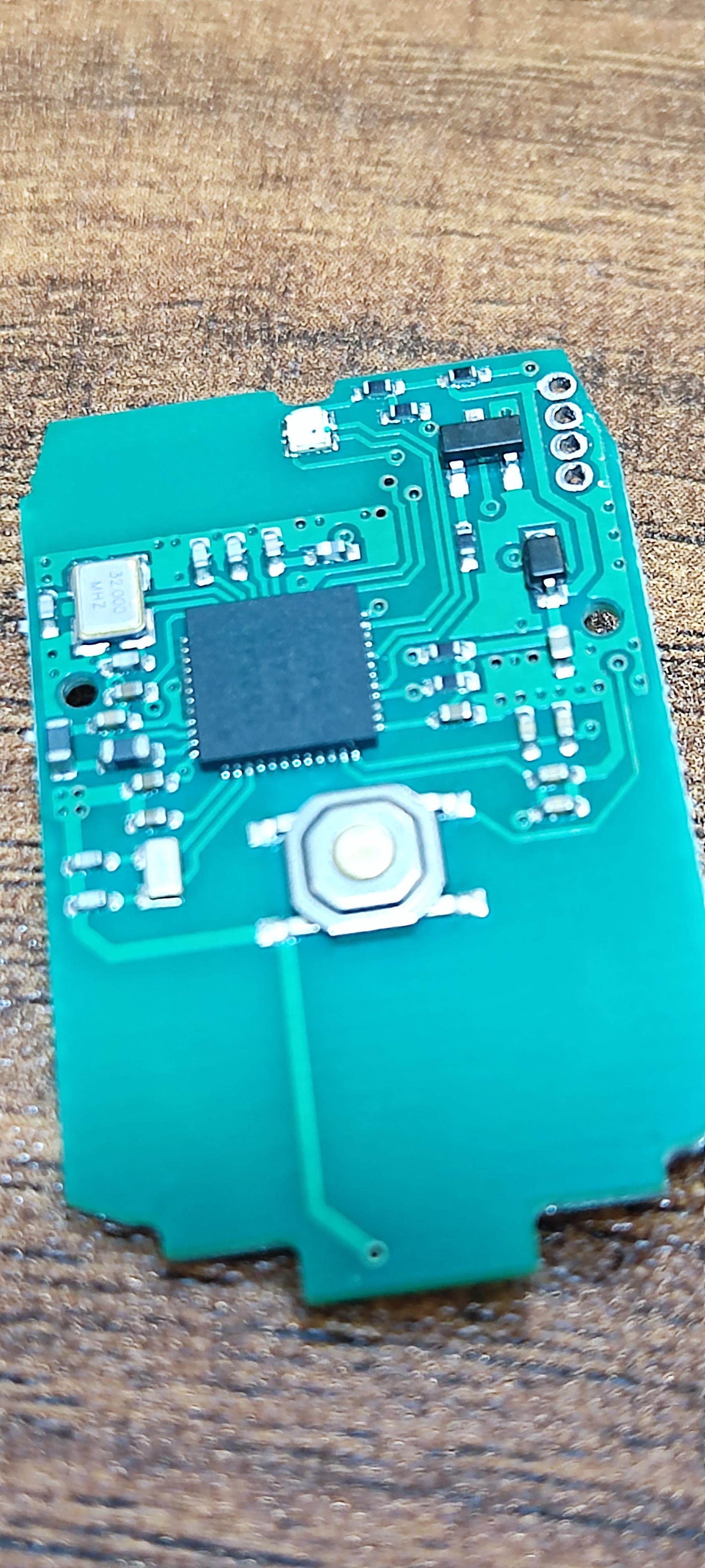
Posted at 2023-07-28 by parasquid I just got myself one of these. Cute litlle things :P I've initially flashed the nrf52832DK image and have been trying to get the pin assignments. It's been only a few minutes and I've only so far found that D17 is the green LED, and D20 is the red LED. The button is at D13. and the buzzer is at D14 For board definitions I think just pasting them in the forum is fine (at least that's what I do, and where I look for others' board defs as well). Posted at 2023-07-28 by parasquid Found some interesting links while looking for amiibo related stuff :P https://www.omniibo.com/ Nice work! Posted at 2023-07-29 by @fanoush Oh, just noticed this, ordered some from different shops, let's hope I'll get nrf52 too. Do you have a photo of pcb? Posted at 2023-07-29 by parasquid Here you go :) The antenna performance seems to be quite bad while inside the plastic case though :( I was only able to connect to it every few tries and will often get disconnected, while having it outside of the plastic caseis more reliable. Attachments: Posted at 2023-07-29 by parasquid What I did find work well is this one: http://www.radioland-china.com/1730323-1730323_2575611.html Bought a few of these on AliExpress a couple of years ago (before the chip shortage): https://www.aliexpress.com/item/32965114958.html Someone wrote custom firmware for this beacon (not Espruino): https://github.com/an-erd/ble_beacon Posted at 2023-07-29 by @fanoush Thanks, looks like optional 32kHz crystal is there too and enabling DC/DC regulator is supported too (reference schematics here). Don't see nfc pins going anywhere, maybe on the other side? Coul you perhaps make a photo of the other side too? The led may be RGB so maybe third pin could be connected too? two or three gpios next to swd pins (D22,23,24) look grounded, maybe it could be cut and connected to blue LED instead. Posted at 2023-07-29 by @fanoush
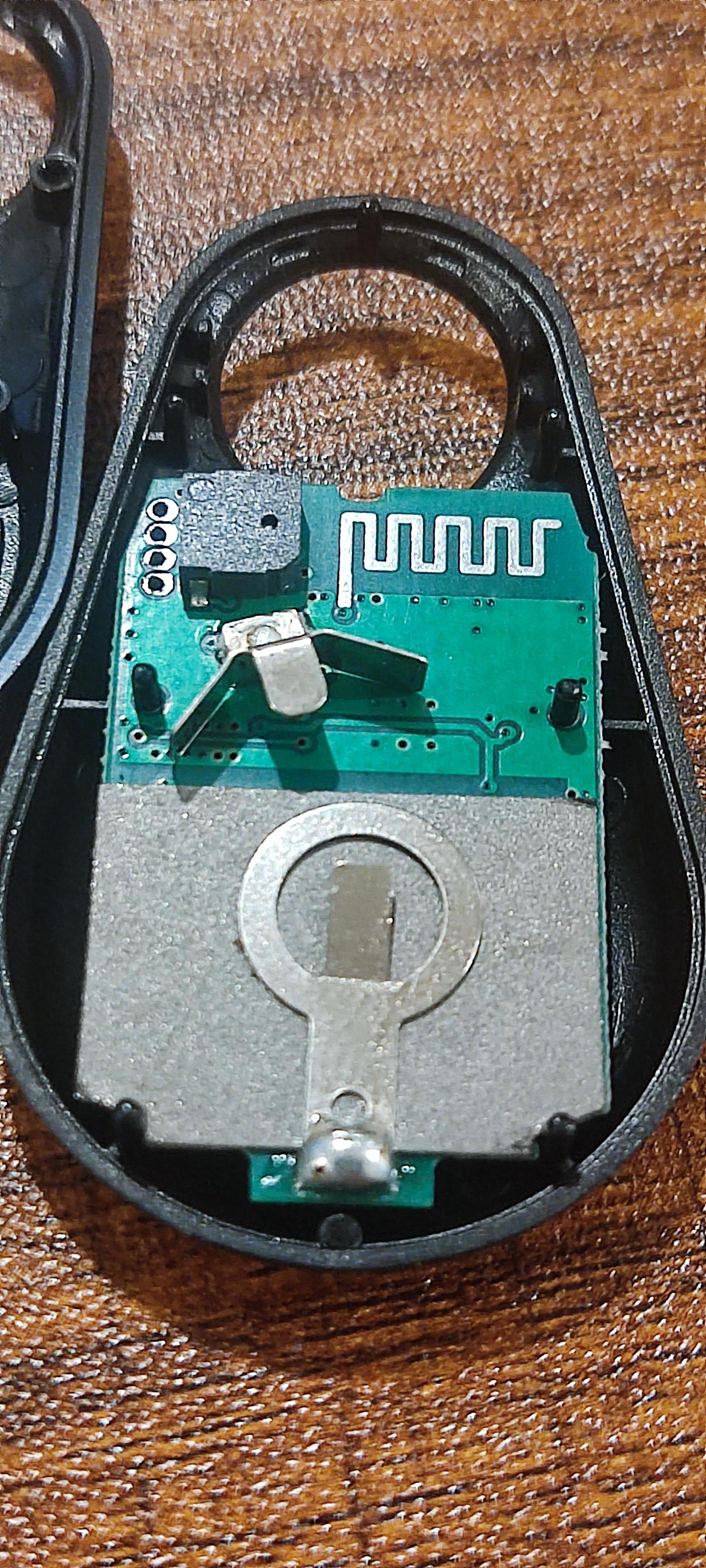
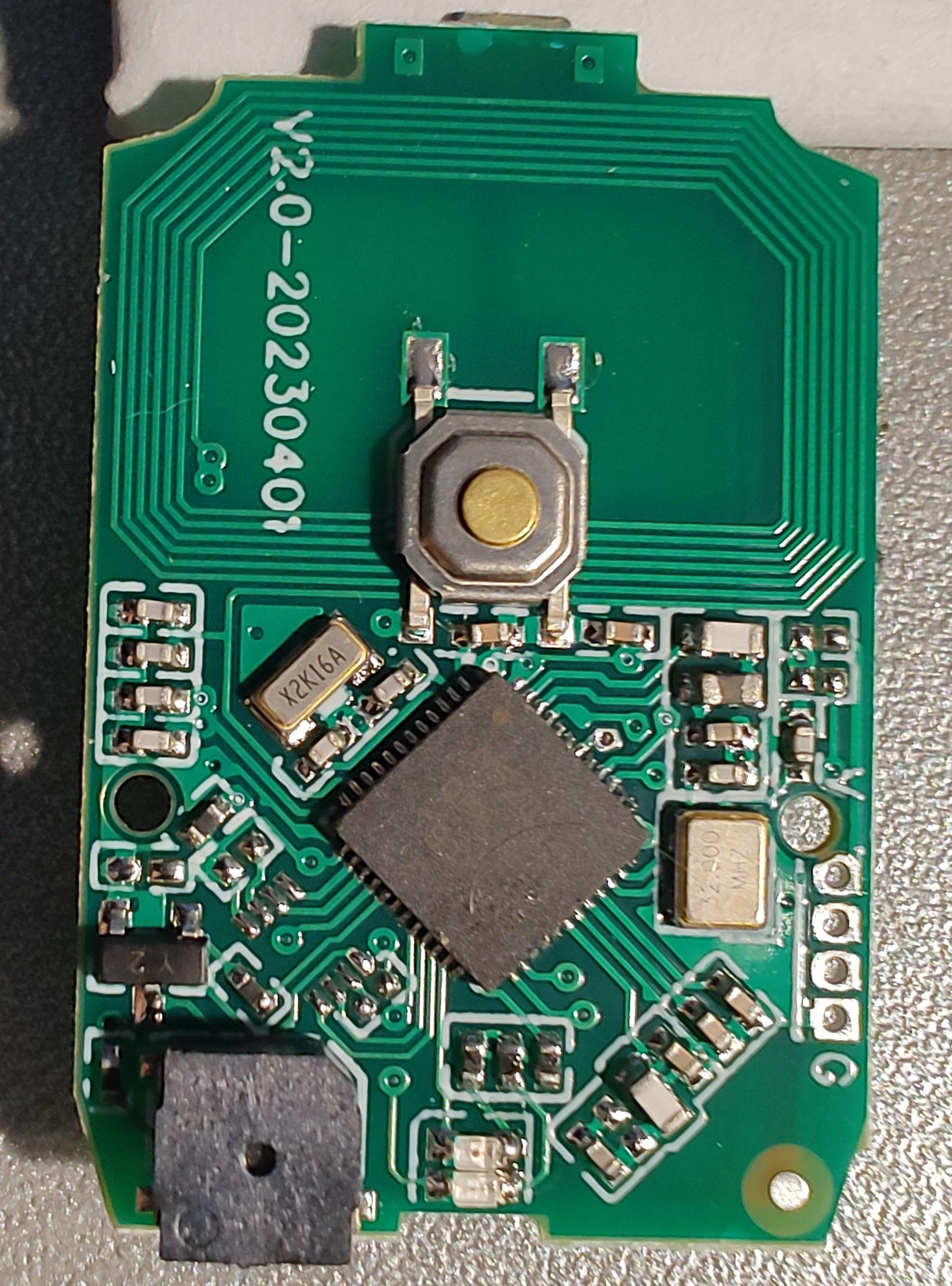
Oh, the price looks decent there and shipping does not increase when increased quantity. I never got those before since they were always relatively expensive (~$10 plus ~$4-5 shipping when other 52832 boards were $4 and 52840 dongle was for $6) but they look cheap now from this seller, no nfc or piezo though. Posted at 2023-07-29 by parasquid Sure, here you go. There's this grey thick sticker (maybe insulation rf shield?) behind the battery which could be where the nfc antenna are?). Not sure about the LEDs; I've looped through all the 32 pins and they are the only ones that light up. It's possible it's RGB but the LED module itself (near the top of the first picture) has four traces; two beside each other (which are likely the D17 and D20 pins) one going to a via and one going to what are probably resistors. Attachments: Posted at 2023-07-29 by @fanoush thanks, yes the third led does not look connected, just guessing that those combined leds are typically rgb so the b might be there, just not connected to any trace Posted at 2023-07-30 by DanTheMan827 Here's the board definition I've made. LED1, and LED2 are functional as red/green. Speaker is in the definition, but it doesn't show up in espruino for some reason... I just use D14 directly. There are multiple boards all being sold under the AmiiboLink name, but they include different firmwares and have different physical layouts. Pin assignments so far appear to be the same. https://imgur.com/a/K8Wp6Rp Someone else has also taken pictures of another variant with rechargeable battery. Attachments: Posted at 2023-07-30 by @fanoush Thanks, sadly some of those seem to be cost optimized - no 32kHz crystal,no inductors for dc/dc. However they do have nfc antenna visible. I wonder where it is on the pcb that parasquid posted and why it is not around the button like on others. If it is under battery then it doesn't look very optimal. Oh, and BTW I posted wrong nrf52832 reference schematics link before, the correct for this QFN48 package is here so now I see NFC pins are in fact going somewhere. Posted at 2023-07-31 by DanTheMan827 The antenna is under the battery, the “sticker” is a shield, and yes, you have to place the device button side down for it to read on some scanners like the Nintendo Switch. The intended purpose of the AmiiboLink branded ones is to emulate amiibo dumps, so they definitely have NFC connected, and it works with espruino just fine… I’m not sure about NFC on the round BLE beacon PCB. Posted at 2023-08-15 by @fanoush Just to let you know that I ordered few of them from different sellers and yesterday I got them. Two are exactly the same as the one @parasquid posted and third one is the variant from this photo https://i.imgur.com/ZUWZ4vp.jpeg - this one looks worse as the opposite side of BLE antenna is populated by components - probably not very good design. First two advertise as AmiLoop, the third one is AMIIBOLINK. My phone with NFC TagInfo sees all of them as NTAG215, the AMIIBOLINK even has some data prefiled out of box. All are nrf52832 so not bad for the price (~US$9 including VAT and shipping). Finally I have some nrf52 devices with NFC to play with :-) Posted at 2023-08-15 by DanTheMan827 Does anyone know how I could define a SPEAKER in the board config? As it is now I just use D14 directly, but it would be nice for compatibility if there was just a way to define it as SPEAKER. It seems like espruino should support it, but it doesn’t seem to for me Posted at 2023-08-15 by @MaBecker have a look at section devices eg. board MDBT42Q.py. Posted at 2023-08-16 by parasquid I think you can just define it and it will work but I'm not sure (will need to read the sources that expand the json into def configuration). I might be able to get some time to experiment with this later this week (but not with the amiibo since it's a bit difficult to flash that one, the xiao ble has a usb bootloader that makes flashing. abit easier since I can just drag the hex file into the pseudo-filesystem). Posted at 2023-08-16 by parasquid One possible alternative would be to define the SPEAKER const in some sort of bootup file (or even just at the top of the source file to be uploaded) and let it be equal to D14 Posted at 2023-08-17 by @fanoush Just tried and the SPEAKER definition only defines the SPEAKER_PIN for C source to use. Check Here is MICRORBIT2 way. Posted at 2023-08-18 by @fanoush
just noticed that on this PCB the D16 pin is brought to place with unpopulated something possibly third LED. So if one would sacrifice 2nd LED there would be 2 pins D17,D16 for I2C to possibly add something or use it as serial console. BTW I flashed Espruino over SWD to this and had my first NFC experience with Espruino, it works quite well :-) I even tried WebNFC in Chrome on Android and it worked too. However for some reason the Samsung Internet browser (based on Chrome too) does not work. I see no error but it does not get any NFC data when I tap it and also it does not ask for NFC permission like Chrome does. Posted at 2023-08-18 by @fanoush BTW did you guys get some fake Amiibolink tags with something else inside? There are sellers with suspicious low prices like https://www.aliexpress.com/item/1005005726070115.html Posted at 2023-08-23 by parasquid Ah, this is something I'd like to try as well (NFC) :D Sadly I misplaced my puck.js and while I can prototype on the pixl.js it's a bit too bulky to try and place on my keychain. Nice to know that this one is good enough for NFC Posted at 2023-08-30 by @fanoush Tried to play some simple tunes via piezo as per https://www.espruino.com/Making+Music and it is not very loud. So these are not like those you stick to lost baggage that make really loud sound. I wanted to pair it with Bangle as alarm clock beep or for some notification alerts but it is too quiet for that. It is louder than piezo in Bangle 1 but not by that much. Maybe if I make a hole in the body where the piezo is, it will be better. Posted at 2023-08-30 by @fanoush I got those very cheap ones and they are OK. Attachments: Posted at 2023-09-01 by @fanoush Was checking power consumption to use the CR2032 battery sensibly. Used meter with mA scale with two fractional digits (have better one but couldn't find right cables :-).
LED is over 1mA (1.7? forgot exactly), analogWrite drops it down and it is still visible Piezo (tested with board that parasquid posted in post #5)
Did the measurements because I noticed E.getAnalogVref() gives voltage below 2.5V for the tag where I tested the piezo while other gave me 3.0V. So looks like I have basically killed the battery when trying to play sounds :-) Posted at 2023-09-01 by parasquid Ah! No wonder I thought the battery went flat so fast. Thanks for the piezo hint (I tried playing a beep when the button was pressed but I reset the pin after the button is depressed). Posted at 2023-09-01 by @gfwilliams Wow, it's surprising about the piezo - my understanding was that they didn't actually draw much power at a voltage... that they were more like capacitors where the change of voltage took power. Maybe something is shorted on your device? I guess there may also be a resonant frequency where the piezo actually makes a decent amount of noise. So just to be clear, you actually bought https://www.aliexpress.com/item/1005005726070115.html and that's what is in the picture above? Looks like a total bargain. Posted at 2023-09-01 by @fanoush
Yes, exactly. Getting two with untracked shipping would be $9.75 total including VAT and shipping for me. I actually got three with tracked shipping so it was $5.6 a piece :-) Yes 32mA looks like short, maybe the battery cannot give much more than that, not sure what the wiring can be to work like that. Posted at 2023-09-01 by @fanoush
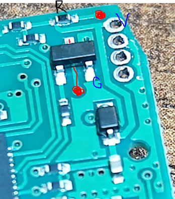
it is GND -> some transistor/FET marked Y2, switched by pin D14 -> one side of piezo -> 12ohm piezo/speaker -> 10ohm resistor -> VCC so 22 ohm in total between VCC and GND when D14 is low (more precisely 22 ohm between VCC and top of the FET) That is a bit strange because I=U/R = 3/22 ~= 136mA but I guess that battery cannot give more so the rest is internal resistance of battery EDIT: attached picture - red are both sides of the speaker, R is 10 ohm resistor, V is VCC, G is GND Attachments: Posted at 2023-09-01 by @fanoush So it is not piezo but something called magnetic buzzer, matches this picture and description https://www.aliexpress.com/item/1649570962.html EDIT: or this https://www.quartz1.com/price/techdata/VS5030B.pdf Posted at 2023-09-04 by @fanoush I tried to replace this magnetic buzzer by piezo but it does not work, it makes no sound, found explanation here https://www.murata.com/en-eu/support/faqs/sound/sounder/char/sch0007 - "You cannot produce a sound from a piezoelectric sounder by simply replacing an electromagnetic buzzer with a piezoelectric sounder in this circuit." I also found another buzzer from similar cheap tracker tag and that one is 15ohm and is much louder. sadly it is also quite a bit bigger so won't fit inside. It looks like this one https://www.aliexpress.com/i/1005005047243506.html Anyway the one on the board posted by parasquid is still not that bad, the other boards have the 10 ohm resistor replaced by higher values and those are more quiet. Also I don't see diode there. As for the SPI flash pinout on the cheap NFCBoxLink ones I got last time - it really matches USON-8 package - VCC,GND,/WP,/HOLD pins are all in correct place and VCC, GND are connected. It is same SPI flash package as used on Raspberry Pico board - found 2MB chips here https://www.aliexpress.com/item/1005004379141351.html - will try to kill at least one NFCBoxLink board by adding it via reflowing by hot air. It is not that much useful there, I know, but still :-) Posted at 2023-09-30 by @fanoush
So I got couple of those W25Q16JVUXIQ USON-8 2x3mm flash chips from that aliexpress shop and tried one with this Amiibo board and it works :-) Got flash ID from the chip - 239, 64, 21 = 2MB winbond flash :-) Photos here https://ibb.co/album/yhhkwZ, left = modified board with W25Q16JVUXIQ added (I also previously removed buzzer, was trying to add piezo or something else), right another original board with no modification Still, it is probably not that much useful, but I simply wanted to try :-) EDIT: and BTW the shop lowered the price even more https://www.aliexpress.com/item/1005005571264919.html I see it as US $2.70 including VAT. Ordered another two pieces with $2.77 aliexpress saver shipping so it was total US $8.17 including shipping for two = about $4 for one :-) let's see if I really get it with this untracked shipping. Posted at 2023-09-30 by @MaBecker Nice work! I bought some in April and got fake ones..... Will check for a dealer that ships to Germany. Posted at 2023-09-30 by @fanoush
Oh, bad luck. All I got were good nrf52832, no issues at all. Now I have 3 flashed with Espruino, each board different variant, and also got couple of spare unused ones of the third variant - could send you some to Germany if you don't find good seller. Only one variant has buzzer that is actually audible from a distance, the rest is very quiet so the buzzer is mostly worthless - maybe good as a feedback that you clicked the button but the microswitch click is good enough for that too. Or maybe as a feedback that NFC communication started but when using the phone it already vibrates for that. Posted at 2023-10-02 by @MaBecker @fanoush - just send you a privat message. Posted at 2023-10-02 by @fanoush
Just a followup - I found out that I bought W25Q16JVUXIQ where the last Q means it is permanently in Quad SPI mode after reset and this mode cannot be cleared. However normal SPI commands still work in this mode so it is OK, the only difference is that /WP and /HOLD pins are data pins and its classic functionality is disabled which is actually good for me as those pins are floating (in theory it is even possible to wire them from unpopulated pull up resistor pads to some nrf pins to have quad mode working but it is not worth it) So everything should work as floating WP or HOLD would not interfere with writes however I could not make writes work with software SPI! All other SPI commands worked - getting ids , putting in and out of sleep, reading unique 64bit id, reading all 3 status registers, write enable (0x6) (the WE bit in status register is set), even the writing or erase command (0x2, 0x20) would clear the WE bit in status register but the data did not change. Checked various flash protection bits and everything was disabled as it should be by default according to datasheet but still nothing. So I built 2MB SPI flash storage area into the firmware by adding and the espruino code did not work too So I enabled hardware SPI in the build and tried that and suddenly everything worked. The very same lines now started to work, I even saw for the first time the busy bit set in status register when erasing And what is interesting is that since then also the software serial and the builtin espruino flash storage started to work - I could erase again and write different data and it all works now. So not sure what really happened. Did not try removing battery yet if it breaks again, will try. Posted at 2024-05-07 by @fanoush Just FYI this Amiibo is probably quite popular so there are several additional models. There is still this basic keychain type for ~ $4USD see e.g. https://www.aliexpress.com/item/1005006521163109.html however now some sellers are part of the "choice delivery" offer with free returns and free shipping over 10 USD so when getting more they are really cheap now. There is $8 model with li-pol battery inside and usb-c charging - I just received one (from same seller, see previous link) - see https://ibb.co/album/CKkBWt it has same quiet buzzer and has four leds, two blink when you push button, two light up when it is put on charger so not sure how many gpios are connected to them - 2 or 4. There are also some $15-$20 models with display see e.g. https://www.aliexpress.com/item/1005006770284160.html some have li-po battery inside, some have only CR2032 so check the listing details. I did not get that one yet. They are all nrf52832 based. The one with display sometimes use name "pixl" or "pixl.js" since it was perhaps inspired by Espruino pixl.js and uses same or similar display - google "amiibo pixl.js" for details or check this https://github.com/solosky/pixl.js/ looks like there are several revisions of the hardware one having OLED screen. Posted at 2024-05-07 by @thyttan
Do you know if there's a reliable way to get that one with louder buzzer? What kind of sounds can it produce? Could I connect it to my Bangle to have it act as a small speaker? Posted at 2024-05-07 by @gfwilliams Thanks! Interesting about the Pixl.js one! I can understand the name Pixl but adding '.js' on the end is really strange... I just hope I don't end up with people buying the Espruino Pixl.js and getting fed up it doesn't do the loot box things out of the box Posted at 2024-05-07 by @fanoush
No, I don't even know which seller it was and even then the stock could change. But I bought 10 pieces of bigger "7525 Passive" one from https://www.aliexpress.com/item/32864653388.html and desoldered the small one and wanted to solder some thin wires to it put it to some space inside (it does not fit on the PCB and the case is too thin there anyway), I verified it fits in one place in the center where the thin hole is but did not actually finish it. With the slightly bigger one with rechargeable battery it could be done too there is even more space inside but maybe desoldering the buzzer on that one may be more complicated without hot air. However the rechargeable battery could last longer with the buzzer than CR2032. Posted at 2024-05-08 by @fanoush So I tested the $8 one with rechargeable battery and I have mixed feelings about it. First I measured current drawn from battery with original firmware when it is sleeping and got ~ 6uA. This is not bad at all if my meter shows correct value. Then I flashed Espruino build I already had for those small $4 keychains and it worked while debugger was attached over SWD but when I disconnected debugger it went into reboot cycle blinking the LED. After some head scratching I figured out it is missing support for internal nrf52 DC/DC! After building another firmware with this disabled the reboot loops stopped. Interesting that it worked while debugger was attached. Probably the DC/DC has different modes based on current and with low current it rebooted. Then I tried to figure out LEDs etc. It is still the same, there is one (RED) led on pin D20 however this one is not visible from outside at all! It is next to 32MHz crystal on the back of the device. Then the LED2 is D17 and this is visible under the blue button. It is actually pair of two LEDs from both sides. Then there is another pair but it does not go to nrf52 at all, it shows charging state and goes off when the charger chip stops charging full battery. No other extra pin is used, even no analog pin reads battery voltage so you don't know how much is left. They probably still kept original CR2032 design. Maybe checking Then I tried buzzer and this is the worst bit in a way. When trying previous code Perhaps mix of DC/DC disabled with weak voltage regulator and/or missing/weak capacitors cannot cope with the current drawn by magnetic buzzer even with duty cycle of 0.96 (i.e. only 4/100 on, 96/100 off)! I found out it does not reboot immediately when I set it >=0.973 however it still reboots when BLE radio draws more on connect/disconnect. 0.98 seems to be safe enough but the sound is not very loud. However it is similar to most of the other keychains (so quite poor). Unfortunately my guess that li-po battery could give more current and louder sound was wrong. So it is still quite capable device for the money when only button/led/BLE/NFC is needed but the design could be better. I'll see how long the battery lasts. Too bad there is no spare GPIO going to any trace to reuse. However since the analog pins on the nrf52 are next to each other I can perhaps solder some voltage divider from battery to the middle of them and won't damage anything else. Then I can pick the best one to read the value. They are tiny but 4 of them is big enough area I guess. Posted at 2024-06-02 by @fanoush So now I got also the "pixl" one, size comparison is here https://ibb.co/album/MZPf8P It has Li-Po battery and even 2MB SPI flash which shares SPI with the ST7567 LCD It is relatively expensive compared to other ones, got one for 14 USD (which is even more than the Magic 3 watch) however it has NFC and passive B/W display so may have other use cases. And today when I searched it on aliexpress again I got the "pick 3 items" ChoiceDay deal and it was only for $8 so got few more. And BTW in same deal the simple keychain amiibo is for $2.69 including VAT/shipping. So you may try searching aliexpress for "pixl" or "amiibo", maybe you'll get the deal too. There is no buzzer and the rocker switch on the top acts as 3 buttons (uses 3 gpios). Three pads on PCB near the NRF52382 corner are RST,SWDCLK,SWDIO so the RST could be repurposed for something. Unlike with the bigger one without display here the battery voltage is connected to analog pin so you can get the voltage. Also this one has the optional inductor so internal DC/DC can be enabled and works fine. Posted at 2024-07-03 by @fanoush
Since that time I had simple interval checking voltage every second and toggling LED if it is below 3.27V and today I noticed it started blinking and voltage is 3.18V now. So it lasted about 2 months on single charge just advertising and sitting on table (Date() says February 25 1970), that is very similar to smartwatches like Magic3. And even if I can't measure battery voltage directly the getAnalogVRef can be used to detect low battery when it gets below 3.3V. Posted at 2024-07-30 by yngv126399 @fanoush Seems like you got pretty far with the pixl version. I've just received one with the LCD and I'd like to pursue getting the screen going. Have you made a board file for it you can share? I've never used NFC before so I'm not sure how to enable it (other than making sure D9/D10 are NOT built as regular GPIOs). Posted at 2024-07-30 by yngv126399 I have it running now: display, buttons, led, backlight. But spi flash is not behaving (I have had this issue with a few other SPI flashes on watches). Builds OK, Storage seems to accept writes, but when you go to read, the files soon disappear. I've tried with build DEFINE for explicit sleep/wake, doesn't help. Posted at 2024-07-31 by @fanoush Nice, I only had basic board file from other amiibos with no display or SPI flash storage defined, for testing display I used https://www.espruino.com/ST7565 . Did you enable native pixl.js display driver (possibly including bootloader support)? BTW, one pixl board I got works but has high power draw no matter what I do and dies in few days, others are fine. Visually they look identical, no visible shorts or something. Will try enabling spi storage files and test writing. For NFC nothing special is needed, just enabling in board file https://github.com/espruino/Espruino/blob/master/boards/PIXLJS.py#L35, easiest test is calling http://www.espruino.com/Reference#l_NRF_nfcURL and phone will find it and open browser Posted at 2024-07-31 by yngv126399 Cute little thing... Attachments: |
Beta Was this translation helpful? Give feedback.
-
Posted at 2023-07-14 by DanTheMan827
I have a device called the “Amiibo Link”, it’s a board that can be found for around $8 or less on AliExpress.
Inside is an NRF52832 512/64KB, red / green LEDs, speaker, button, and an NFC antenna.
I have a board definition, but I’m not sure of the process involved, or if you’d even want to add it.
SWD pins are accessible through an unsoldered header, or even with oscilloscope clips if you’re careful to not scratch the solder mask on the ground plane.
Although I’m not quite sure how to assign a device like the speaker in the definition. To use it, 50% PWM at various frequencies changes the tone, and high or low on the pin seems to disable it altogether. Different PWM values do also change the tone and volume slightly.
Attachments:
Beta Was this translation helpful? Give feedback.
All reactions