Implementation of Polyanya in Rust! Polyanya is a any-angle path planning algorithm.
WASM demos made with Bevy are available here.
- Pathfinding using Polyanya: Efficient any-angle path planning algorithm for navigation meshes.
- Multi-layer Navigation Mesh Support:
- Overlapping navmeshes for 3D navigation (floors, bridges, ...).
- One-way layers for directional movement.
- Conditional layer traversal with the ability to enable or disable layers.
- Layers with different traversal costs for more realistic pathfinding.
Navigation meshes can be built by specifying their outer edges and inner obstacles:
use glam::vec2;
use polyanya::*;

// Build a mesh from its outer edge
let triangulation = Triangulation::from_outer_edges(&[
    vec2(0., 6.), vec2(2., 5.),
    vec2(2., 4.), vec2(1., 4.),
    vec2(1., 3.), vec2(2., 1.),
    vec2(4., 1.), vec2(4., 2.),
    vec2(7., 4.), vec2(7., 0.),
    vec2(12., 0.), vec2(12., 3.),
    vec2(11., 3.), vec2(11., 5.),
    vec2(13., 5.), vec2(13., 7.),
    vec2(10., 7.), vec2(11., 8.),
    vec2(7., 8.), vec2(7., 7.),
    vec2(5., 7.), vec2(5., 8.),
    vec2(0., 8.),
]);
let mesh = triangulation.as_navmesh();

// Get the path between two points
let from = vec2(12.0, 0.0);
let to = vec2(3.0, 1.0);
let path = mesh.path(from, to);

assert_eq!(
    path.unwrap().path,
    vec![
        vec2(7.0, 4.0),
        vec2(4.0, 2.0),
        vec2(3.0, 1.0)
    ]
);
They can also be built by manually specifying vertices and polygons for complete control. The following produces the same mesh
use glam::vec2;
use polyanya::*;

// Build a mesh from a list of vertices and polygons
let mesh = Mesh::new(
    vec![
        Vertex::new(vec2(0., 6.), vec![0, u32::MAX]),           // 0
        Vertex::new(vec2(2., 5.), vec![0, u32::MAX, 2]),        // 1
        Vertex::new(vec2(5., 7.), vec![0, 2, u32::MAX]),        // 2
        Vertex::new(vec2(5., 8.), vec![0, u32::MAX]),           // 3
        Vertex::new(vec2(0., 8.), vec![0, u32::MAX]),           // 4
        Vertex::new(vec2(1., 4.), vec![1, u32::MAX]),           // 5
        Vertex::new(vec2(2., 1.), vec![1, u32::MAX]),           // 6
        Vertex::new(vec2(4., 1.), vec![1, u32::MAX]),           // 7
        Vertex::new(vec2(4., 2.), vec![1, u32::MAX, 2]),        // 8
        Vertex::new(vec2(2., 4.), vec![1, 2, u32::MAX]),        // 9
        Vertex::new(vec2(7., 4.), vec![2, u32::MAX, 4]),        // 10
        Vertex::new(vec2(10., 7.), vec![2, 4, 6, u32::MAX, 3]), // 11
        Vertex::new(vec2(7., 7.), vec![2, 3, u32::MAX]),        // 12
        Vertex::new(vec2(11., 8.), vec![3, u32::MAX]),          // 13
        Vertex::new(vec2(7., 8.), vec![3, u32::MAX]),           // 14
        Vertex::new(vec2(7., 0.), vec![5, 4, u32::MAX]),        // 15
        Vertex::new(vec2(11., 3.), vec![4, 5, u32::MAX]),       // 16
        Vertex::new(vec2(11., 5.), vec![4, u32::MAX, 6]),       // 17
        Vertex::new(vec2(12., 0.), vec![5, u32::MAX]),          // 18
        Vertex::new(vec2(12., 3.), vec![5, u32::MAX]),          // 19
        Vertex::new(vec2(13., 5.), vec![6, u32::MAX]),          // 20
        Vertex::new(vec2(13., 7.), vec![6, u32::MAX]),          // 21
        Vertex::new(vec2(1., 3.), vec![1, u32::MAX]),           // 22
    ],
    vec![
        Polygon::new(vec![0, 1, 2, 3, 4], true),           // 0
        Polygon::new(vec![5, 22, 6, 7, 8, 9], true),       // 1
        Polygon::new(vec![1, 9, 8, 10, 11, 12, 2], false), // 2
        Polygon::new(vec![12, 11, 13, 14], true),          // 3
        Polygon::new(vec![10, 15, 16, 17, 11], false),     // 4
        Polygon::new(vec![15, 18, 19, 16], true),          // 5
        Polygon::new(vec![11, 17, 20, 21], true),          // 6
    ],
).unwrap();
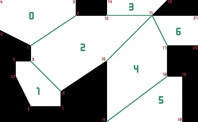
The code above will build the following mesh, with polygons marked in green, and vertices in red:
Check the cpp implementation.
index;micro;successor_calls;generated;pushed;popped;pruned_post_pop;length;gridcost
0;4960.92;6974;4368;4313;3823;21;1123.222637572437;1199.73
This crate seems to generate a few more nodes, but tends to be faster than the cpp implementation. There are a few known cases to still improve it:
- collinear optimisation, when a search node root and interval are all on a same line
- triangle optimisation, when searching in a triangle polygon
- when an intersection is very close to a vertex, it sometimes generates an extra slim search node
- searching start and end nodes is costlier
Compiling this crate with feature stats will output almost the same level of information as the default cpp implementation output.
index;micros;successor_calls;generated;pushed;popped;pruned_post_pop;length
0;2990.083;6983;7748;4314;3828;21;1123.2228
The verbose feature will give the same output as setting verbose to 1.
        pushing: root=(993, 290); left=(989, 303); right=(1001, 288); f=1020.21, g=0.00
        pushing: root=(993, 290); left=(984, 301); right=(988, 303); f=1016.98, g=0.00
        pushing: root=(993, 290); left=(982, 300); right=(984, 301); f=1016.06, g=0.00
        pushing: root=(993, 290); left=(994, 285); right=(981, 299); f=1014.84, g=0.00
popped off: root=(993, 290); left=(994, 285); right=(981, 299); f=1014.84, g=0.00
        intermediate: root=(993, 290); left=(988, 282); right=(981, 299); f=1014.84, g=0.00
        pushing: root=(993, 290); left=(977, 299); right=(980, 299); f=1015.14, g=0.00
        pushing: root=(993, 290); left=(984, 280); right=(976, 297); f=1014.84, g=0.00
popped off: root=(993, 290); left=(984, 280); right=(976, 297); f=1014.84, g=0.00
        pushing: root=(993, 290); left=(973, 296); right=(976, 297); f=1014.84, g=0.00
        pushing: root=(993, 290); left=(970, 295); right=(973, 296); f=1014.86, g=0.00
        pushing: root=(993, 290); left=(967, 294); right=(970, 295); f=1015.01, g=0.00
        pushing: root=(993, 290); left=(965, 293); right=(967, 294); f=1015.28, g=0.00
        pushing: root=(993, 290); left=(977, 276); right=(965, 293); f=1015.58, g=0.00
        pushing: root=(993, 290); left=(983, 279); right=(979, 277); f=1023.95, g=0.00
popped off: root=(993, 290); left=(973, 296); right=(976, 297); f=1014.84, g=0.00
popped off: root=(993, 290); left=(970, 295); right=(973, 296); f=1014.86, g=0.00
popped off: root=(993, 290); left=(967, 294); right=(970, 295); f=1015.01, g=0.00
popped off: root=(993, 290); left=(977, 299); right=(980, 299); f=1015.14, g=0.00
popped off: root=(993, 290); left=(965, 293); right=(967, 294); f=1015.28, g=0.00
popped off: root=(993, 290); left=(977, 276); right=(965, 293); f=1015.58, g=0.00
        pushing: root=(993, 290); left=(963, 292); right=(965, 293); f=1015.58, g=0.00
        pushing: root=(993, 290); left=(961, 291); right=(963, 292); f=1015.94, g=0.00
        pushing: root=(993, 290); left=(971, 273); right=(959, 289); f=1017.13, g=0.00
...
The mesh files used in tests are coming from the cpp implementation and are available under MIT license.


