Advanced Lane Finding Project
The goals / steps of this project are the following:
- Compute the camera calibration matrix and distortion coefficients given a set of chessboard images.
- Apply a distortion correction to raw images.
- Use color transforms, gradients, etc., to create a thresholded binary image.
- Apply a perspective transform to rectify binary image ("birds-eye view").
- Detect lane pixels and fit to find the lane boundary.
- Determine the curvature of the lane and vehicle position with respect to center.
- Warp the detected lane boundaries back onto the original image.
- Output visual display of the lane boundaries and numerical estimation of lane curvature and vehicle position.
Rubric Points
The code for this step is in lines #5 through #41 of the file called utils.py.
I start by preparing "object points", which will be the (x, y, z) coordinates of the chessboard corners in the world. Here I am assuming the chessboard is fixed on the (x, y) plane at z=0, such that the object points are the same for each calibration image. Thus, objp is just a replicated array of coordinates, and objpoints will be appended with a copy of it every time I successfully detect all chessboard corners in a test image. imgpoints will be appended with the (x, y) pixel position of each of the corners in the image plane with each successful chessboard detection.
Non all the images included in camera_cal folder has been used as some of
them has a different number of corners inside the chessboard so, I fixed the
number of corners to (9x6) and then in case the findChessboardCorners fails I
skipped the image.
I then used the output objpoints and imgpoints to compute the camera calibration and distortion coefficients using the cv2.calibrateCamera() function.
In order to test this procedure I applied this distortion correction to the test
image using the cv2.undistort() function and obtained this result:
 Distorted Image
 Undistorted Image
When a test image or a frame from the video is passed to the processing pipeline all of these stages will be performed:
- undistort
- thresholding
- perspective transformation
- Line finding and extraction
- Unwarp and video annotation
- Output
To demonstrate this step, I will describe how I apply the distortion correction to one of the test images like this one:
 Road Distorted
 Road Undistorted
The purpose of this operation is trying to identify as best as possible the lines
that separate the road lanes.
I used a combination of color and gradient thresholds to generate a binary image (thresholding steps at lines #44 through #92 in utils.py and #33 through #47 in warper.py).
In order to identify which combination works best I did many attempts in a separate
notebook and I report here the attempts made.
Basically absolute sobel for gray scale image, Red channel, Saturation in HSL
and V channel in HSV color scheme seemed to offer best performaces.
 Gray scaled image
 RGB Color Space
 HSV color Space
 HLS color Space
 Combined and Warped Image
The code for my perspective transform includes 2 function to determine source
and destination points in the utils.py from line #95 to line #115, and
the output of this functions is used inside the warper class in warper.py from #19 and #21 line and then #63.
In lines #19 and #21 the matrices to perform the transformation are calculated and
then stored inside member variable of the class Warper. in line #63 the real transformation
is done.
I chose the hardcode the source and destination points identifying then by
trial and error point:
The warped images can be seen as last image on the right in the Combined and Warped image figure
I used two approaches to find the lines and I use them both.
Those approaches were suggested during Udacity lesson.
First is the sliding windows approach, where I first calculate an histogram
of the warped image, in order to find peaks along the columns of the images.
One peak in the first half of the image and one from the half to the left hand side.
These peaks will be my starting point for the lane lines.
I will then split the image in slices (I trided different values and then used 25) (the biggest is the number more it takes to perform) horizontally and starting from the peak found before I will looking in a rectangular area centered at the peak and for
pixels with value "1" i.e. (line points).
I will keep those indices in order to extract the pixels from the real image
when the sliding windows process is done.
If the number of pixels found is more than a threshold then I will recenter the
rectangle (using the mean of the position of this points) were I do the search,
in order to follow curves lines.
When all the sliding windows are finished, I will use the indexes list I created
to extract the x and y values of the pixels and then fit a a line with polyfit function
using those values.
This procedure is coded from line #87 to line #188 in line.py
As this sliding window is a quite slow process and then a line does not change
that much from frame to frame, I will used the last found values of x in order
to fit next frame. (from line #191 to line #220 in line.py).
Every (5 frames (but works also for 20)) I will start again sliding windows in order not to introduce additional error.
 Sliding window method
The radius of curvature is calculated in lines between #257 and #274 in lines.py
The method was clearly explained during the lesson, so this code was taken from
lessons.
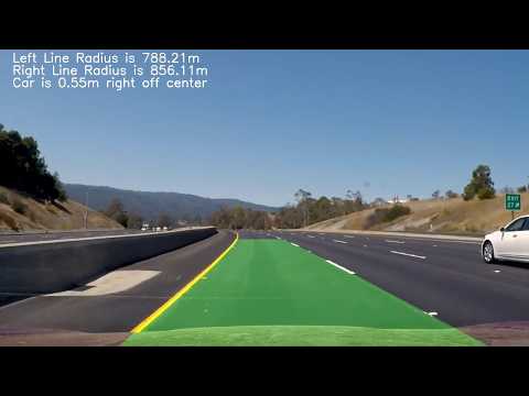
In lines #70 to #72 of the warper.py I transformed back the image in order
to have an area that could be overlapped to the original image.
The green area is the one incuded by the lines found.

My model is really far from being robust. No validation mechanism has been used. Different light conditions make it very likely to fail, as I tried it too on the more difficult videos and does not perform well at all.
- While implementing this I first had problem with camera calibration... why different chessboard with different size were given? Just to make us think or was a mistake? I think that if I have to calibrate my camera (i.e. my phone camera) I will be very careful in taking pictures to the chess board...at least all the chessboard has the same number of corners.
- Second problem: Finding points to do perspective transformmation... they were detected by trial and error so no a specific method were used. I think this should be improved as points may be can be changed also while using different images.
- Thresholding...I tried to use different color spaces to find the lines. As we see in the lesson there are more "robust" color spaces then other. But sometimes thei fail too.
- Annotating the video: The procedure to find how many pixels corrisponds to 1 meter is a caracteristic of the image and the space between lines is decided by regulation of the country where the image is taken...so the code cannot be reused without changes.