This is a matrix multiplication accelerator implemented in Xilinz Zynq Soc. This is a self-learning project for me to learn how to use Vivado and Vitis for SoC design. The accelerator is implemented in the PL part of the SoC, and the host program is implemented in the PS part of the SoC. The host program is written in C and the accelerator is written in Verilog and SystemVerilog. The host program is compiled by Vitis and the accelerator is synthesized by Vivado. The host program and the accelerator are connected by AXI4-LITE interface. The host program gets the input matrices from external UART and sends them to the accelerator. The accelerator calculates the result and sends it back to the host program then the host program sends the result to external UART. A python script is written to send the input matrices to the host program and receive the result from the host program through UART.
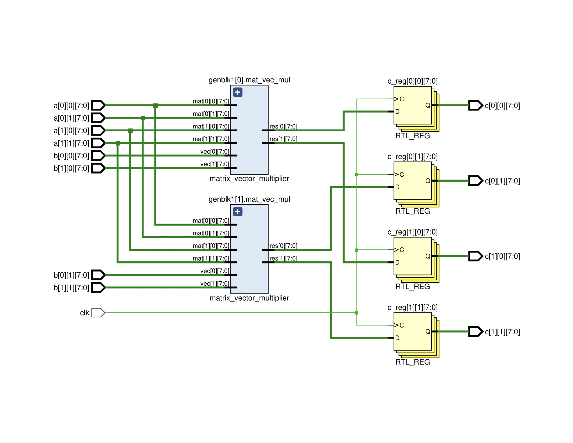
The RTL design of the accelerator of 2x2 matrix multiplier is shown below.

The block design of the accelerator is shown below.

The accelerator has a AXI4-LITE interface but Zynq PS has AXI3 interface. Therefore, AXI interconnect is used to connect AXI4-LITE interface of the accelerator to AXI3 interface of the PS. The base address of the accelerator is set to 0x43C00000.
The host program is written in C. The host program gets the input matrices from external UART and sends them to the accelerator. The accelerator calculates the result and sends it back to the host program then the host program sends the result to external UART. The host program is compiled by Vitis. The host program is shown below.
#include "platform.h"
#include "xbasic_types.h"
#include "xil_printf.h"
#include "xparameters.h"
#include "xuartps.h"

#define ROWS_A 2
#define COLS_A 2
#define COLS_B 2

volatile Xuint32 *mat_mul = (Xuint32 *)XPAR_MATRIX_MULTIPLIER_0_S_AXI_BASEADDR;
XUartPs Uart_Ps;

int initUart() {
    XUartPs_Config *Config;
    int Status;

    Config = XUartPs_LookupConfig(XPAR_PS7_UART_1_DEVICE_ID);
    if (NULL == Config) {
        return XST_FAILURE;
    }

    Status = XUartPs_CfgInitialize(&Uart_Ps, Config, Config->BaseAddress);
    if (Status != XST_SUCCESS) {
        return XST_FAILURE;
    }

    XUartPs_SetBaudRate(&Uart_Ps, 115200);

    return XST_SUCCESS;
}

void send_uart(int *C) {
    for (int i = 0; i < ROWS_A * COLS_B; i++) {
        XUartPs_Send(&Uart_Ps, &C[i], 4);
    }
}

u32 recev_word() {
    u32 word = 0;
    u8 byte = 0;
    int i = 0;

    while (i < 4) {
        i += XUartPs_Recv(&Uart_Ps, &byte, 1);
        word = word | (byte << ((i - 1) * 8));
    }
    return word;
}

void recev_matrix(int *A, int rows, int cols) {
    for (int i = 0; i < rows * cols; i++) {
        A[i] = recev_word();
    }
}

void matrix_multiplier(int *A, int *B, int *C) {
    for (int i = 0; i < ROWS_A * COLS_A; i++) {
        *(mat_mul + i) = A[i];
    }

    for (int i = 0; i < COLS_A * COLS_B; i++) {
        *(mat_mul + i + ROWS_A * COLS_A) = B[i];
    }

    for (int i = 0; i < ROWS_A * COLS_B; i++) {
        C[i] = *(mat_mul + i + ROWS_A * COLS_A + COLS_A * COLS_B);
    }
}

int main() {
    init_platform();
    initUart();

    u32 A[ROWS_A * COLS_A];
    u32 B[COLS_A * COLS_B];
    u32 C[ROWS_A * COLS_B];

    while (1) {
        recev_matrix(A, ROWS_A, COLS_A);
        recev_matrix(B, COLS_A, COLS_B);
        matrix_multiplier(A, B, C);
        send_uart(C);
    }

    cleanup_platform();
    return 0;
}A python script is written to send the input matrices to the host program and receive the result from the host program through UART. The python script is shown below.
import serial
from time import sleep

# Open serial port
ser = serial.Serial("/dev/ttyUSB1", 115200)


# Read data from serial port
def read_data():
    arr = []

    for i in range(4):
        received_byte = ser.read(4)
        int_val = int.from_bytes(received_byte, "little")
        arr.append(int_val)

    return arr


# Send data to serial port
def send_data(data):
    for i in range(4):
        ser.write(data[i].to_bytes(4, "little"))

def mat_mul(A, B):
    send_data(A)
    send_data(B)
    arr = read_data()
    return arr


A = [1, 2, 3, 4]
B = [5, 6, 7, 8]
C = mat_mul(A, B)

# Print result
for i in range(2):
    for j in range(2):
        print(C[i*2 + j], end=" ")
    print()
The result of the python script is shown below.
19 22
43 50
The accelerator is implemented on a Zybo Z7-20 board. The Zybo Z7-20 board has a Zynq-7000 SoC. The Zynq-7000 SoC has a dual-core ARM Cortex-A9 processor and a Artix-7 FPGA. The following figure shows the Zybo Z7-20 board.

The accelerator is implemented on the FPGA.
The UART1 port is used to communicate with python script.