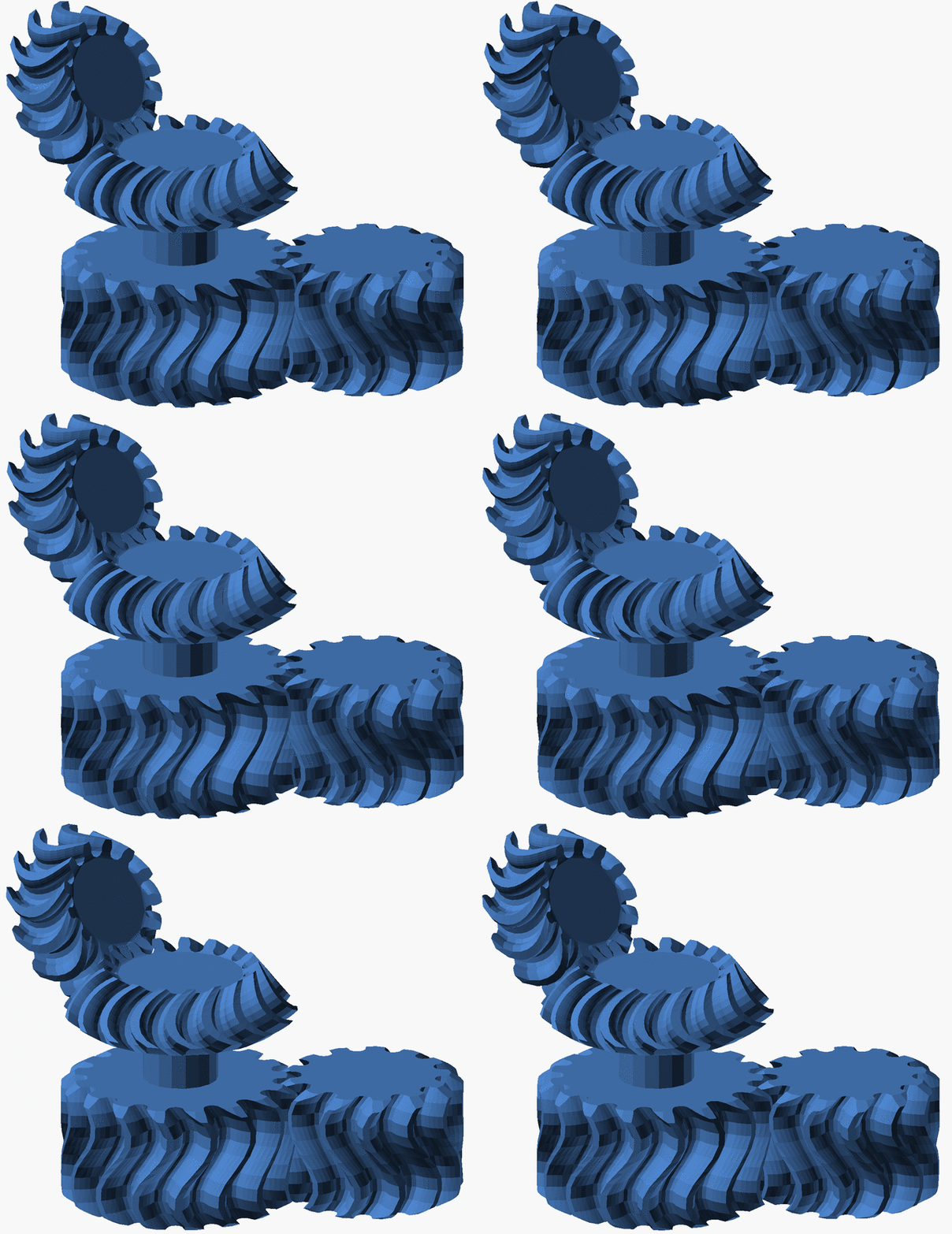
PolyGear is a powerful OpenSCAD library to create spur and bevel gears as a single polyhedron. The library allows full control of the involute tooth profile, including pressure angle, backlash, variable helix angle, addendum, dedendum and profile shifting. The helix angle can be changed along the axis of the gear, allowing to generare and seamlessly switch between straight, spiral, herringbone, zerol and customized profiles.
The gears are constructed in an extremely efficient way, by triangulating a minimal vertex cloud with a single polyhedron. The resulting solids are robust and safe to be further processed by any OpenSCAD operation.
I wrote this library because I was unsatisfied with the existing ones:
- https://www.thingiverse.com/thing:3575
- https://www.thingiverse.com/thing:636119
- https://www.thingiverse.com/thing:1604369
being, to my taste, either too hampered, fragile or computational expensive. My aim has been overcoming these limitations. Do not expect lightening holes or other gimmicks, but comprehensive and efficient control over your gear teeth.
The main library file is well commented, and self-suffice as documentation for the various parameters and commands. If you need more insight please refer to the Knowledge Base and FAQ sections below.
PolyGear requires OpenSCAD v2019.05 or more recent.
Using older version is discouraged, but feasible with minor modifications, see #2.
- PolyGear.scad - main file, the one that you should read and use (and NOT include) in your project
- PolyGearBase.scad - computation of the gear profile and some meshing functions
- PolyGearUtils.scad - collection of more and less trivial complementary functions
- linspace.scad - lightweight library for producing range of points
- shortcuts.scad - a slightly enhanced version of the excellent shortcuts library by Parkinbot
The library uses industry standard terminology and conventions. KHK Gears published an excellent summary which is mirrored in the docs folder for convenience. If words like "module" and "pressure angle" confuse you, please make sure to review it.
If you want to dive deeper in the evaluation/parameterization of the involute profiles, this nice open access paper, is what inspired the computations implemented in PolyGearBase.scad.
You can think about the module as a universal measure of the size of the tooth. Having the same module is the first requisite when evaluating the proper meshing of two gears. It is therefore very deeply rooted into the industry standard and well described in the document from KHK Gears. You could use the radius, but in the long run it would hurt yourself with fractional (likely irrational) number of teeth and/or non meshing gears.
If you really want to go the radius way, you can always use the OpenSCAD resize() function, but you have been warned...
The construction of bevel gears starts from the reference circle of the bottom face. This is always centered around the origin of and lies in the XY plane. Its radius (rref in the figure above) is determined by the module and the by number of teeth (as for spur gears).
The next important parameter is the cone_angle ⍺ defined as half of the vertex angle of the cone on which the teeth of the gear lie.
Finally one needs to define either w or z, the first represents the slant height of the teeth (parallel to the cone face), the second is the height of the teeth (parallel to the cone axis which is the z axis). Preferring w over z ensures matching tooth widths when pairing bevel gears with different cone angles.
At this point the reference radius of the top face is fully constrained and the construction is completed.
This is because the end faces of the teeth of the bevel gears are constructed by folding the end faces of the teeth of a spur gear (which are planar) on the spherical suface centered at the cone vertex and passing by the reference circle.
In the figure above the end-faces of the teeth of the corresponding spur gear are marked in blue. Their projection on the spherical surface is marked in red, as well as the resulting bevel gear. Note that the figure above shows a projection and not the actual folding which the library uses to preserve the length of the teeth.
This kind of construction allows the tooth sides of two meshing gears (with the same w) to be fully in contact, whithout having their ends sticking outside of each other, while still defining the positioning of the gear by means of the bottom face reference circle.
In case you need it, you can quickly compute the distance between the reference circle and the bottom face with the helper function bevel_gear_z_offset().
While developing your design, it can be helpful envisioning gears as smooth cylinders (spur) and cones (bevel) determined by their reference radius. In this way you can focus on specifying their size and positioning. The library will then take care of producing properly meshing teeth on their lateral surfaces.
The example folder collects some complex assemblies constructed with just a few line of codes by empowering PolyGear.
Feel free to drop me an email at pellegrini.dario/@/gmail/./com I am always happy to help and work with you especially if you are a student (note that being a student is a state of mind, you do not need to be a child or enrolled anywhere).
However if you come to me with requests demanding a significant amount of my time and skill set, or you are working on a commercial project, do not expect me to do it for free. It took me years to forge my technical acuity and I will consider working for you only if reasonably compensated. In short: be respectful.
This work is licensed under a Creative Commons Attribution-ShareAlike 4.0 International License.

