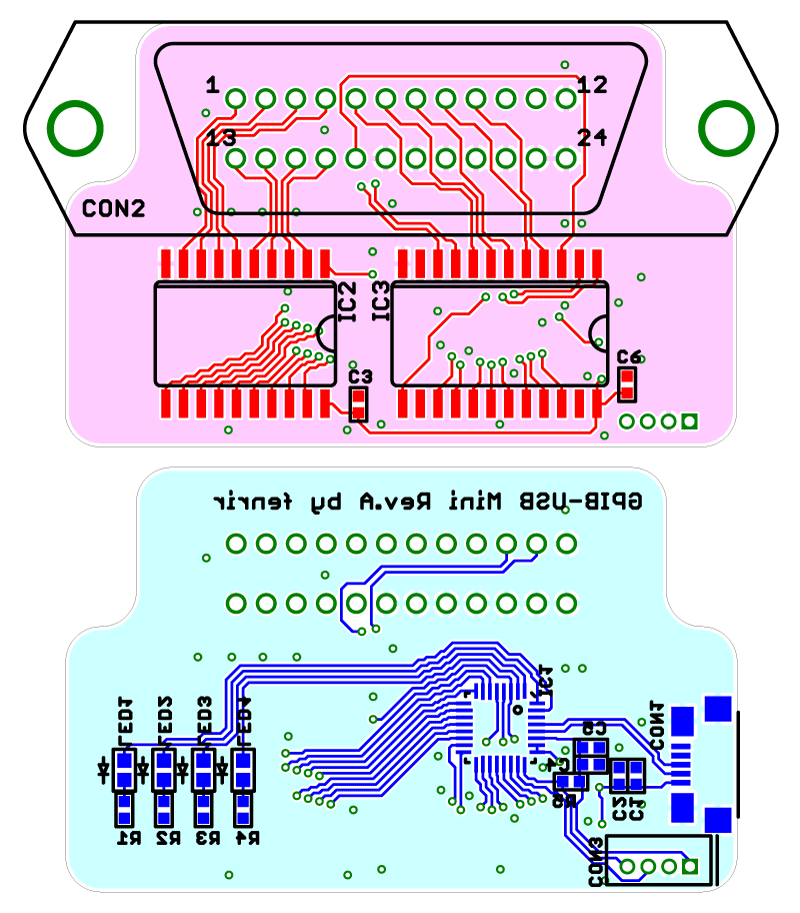
GPIB-USBCDC is an interface bridge between GPIB (HPIB) and USB communication device class. It is Prologix GPIB-USB adapter clone with EFM8 Universal Bee or C8051F38x microcontroller.
- Connect GPIB-USBCDC to the PC. GPIB-USBCDC is recognized as serial port, which will be installed with CDC inf file.
- Other usage is almost same as Prologix GPIB-USB adapter. Please see that product manual.
Nice user manual written by Alessandro Soraruf is available, Thanks! In addition, please set up your device with its address except for zero, in case of bus confliction reported by biergaizi.
EagleCAD files are available (ver.1 schematics and layout. Its components are listed in BOM. The board design is published under Creative Commons Attribution-ShareAlike 4.0 International.
| Part | Value | Package | Multiple |
|---|---|---|---|
| C1, C4 | 1u / 6V3 | 1005 | 2 |
| C2, C3, C5, C6 | 0.1u / 10V | 1005 | 4 |
| CON1 | HRS ZX62R-B-5P | 1 | |
| CON2 | Norcomp 111-024-113L001 | 1 | |
| CON3 | JST ZH B4B-ZR | 1 | |
| IC1 | EFM8UB20F32G-A-QFN32 or C8051F387-GM | QFN32 | 1 |
| IC2 | SN75160BDWR or SN75ALS160DWR | SO20 | 1 |
| IC3 | SN75162BDWR or SN75ALS162DWR | SO24 | 1 |
| LED1 | Red | 1608 | 1 |
| LED2 | Orange | 1608 | 1 |
| LED3 | Green | 1608 | 1 |
| LED4 | Blue | 1608 | 1 |
| R1, R2, R3, R4 | 470 | 1005 | 4 |
| R5 | 1K | 1005 | 1 |
The official binary is published in github release. To build the firmware by yourself, install sdcc (testing with ver 3.3.0 #8604), and just "make" at "firmware" directory of the downloaded code. The generated firmware name is gpib-usbcdc.hex. The firmware code is published under New BSD License.
Connect a GPIB-USBCDC board and a PC via USB debug adapter (UDA) or compatible one. The minimum required programming connections are summarized in the following table. Then, use Flash Programming Utilities. Note: the board may not be recognized by a PC when an UDA is connected via USB hubs. UDA is recommended to connect a PC directly.
| Signal | UDA side | GPIB-USBCDC board side |
|---|---|---|
| C2D | 4th pin | CON3 3rd pin |
| C2CK | 7th pin | CON3 4th pin |
| GND | 3rd pin | CON3 1st pin |
- The project owner's website is Fenrir's BLog.
