-
Notifications
You must be signed in to change notification settings - Fork 132
Deriving FAR values for a wing using Blender 2.7
(Contributed by Taverius)
FAR uses a trapezoidal approximation for aerofoil shapes.
It assumes the shape being described has exactly 4 sides:
- a leading edge
- a trailing edge
- a wing root
- a wing tip
Furthermore, it assumes both the wing tip and the wing root are parallel to each other and the Z-axis. We can see this using the Squad SweptWing for an example:
- Black: Original Squad mesh
- Orange: FAR's trapezoidal approximation of the wing shape
Knowing this, we can then use the following measurements and equations to calculate the various values that are required for a FAR aerofoil part:
Some notes:
- FAR assumes the wing starts at the model origin. Therefore, any parts of the mesh over the y axis should be ignored.
- When producing values for controllable surfaces, one should also measure out the ratio of the surface areas of the entire wing and the moving part, and enter that as
CtrlSurfFrac. In a pinch one can use the value the stock module uses, but these tend to be very rough approximations due the inherent imprecision of the stock model.
(Contributed by Gaiiden)
For this tutorial, we will be using the latest version of the Blender 3D modeling environment at the time of this writing, which is v2.7 and is free to download. If you do not have this tool, the first step for you is to install it onto your computer.
NOTE: This tutorial was done on a Windows-based system. Also, this is me having used Blender for all of 3 days :P
The KSP .mu model format requires a custom importer to be added to Blender in order for us to load them in the program.
A custom importer has already been created by the community and can be downloaded here.
You can place the .zip file anywhere on your system, whether in the KSP folder or the Blender AddOns folder or a location elsewhere. There is no need to unzip the package, Blender expects to import the addon by loading a .zip file.
Once you have done this, load up Blender and pull out the right-side frame using the grab handle.
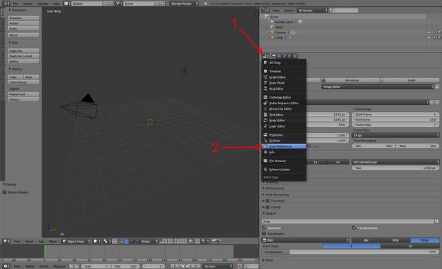
Then click the current editor type button (1) and select User Preferences (2).
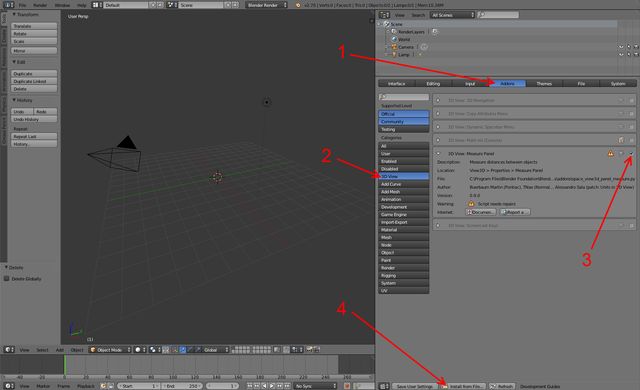
Now navigate to the Addons pane (1) and before we install the .mu importer while we're here let's also enable the Measure Panel plugin, which you can find in the 3D View category (2) and enable it by clicking the check box (3).
Now let's add the .mu importer by clicking the Install from File... button (4)
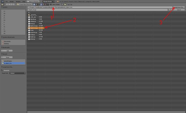
Use the file system navigator or enter the path to the directory where you stashed the .Zip archive you downloaded earlier off the KSP forums (1).
Then you will want to select the .zip file (2) and click the Install from File... button (3) - or just double-click the .zip file.
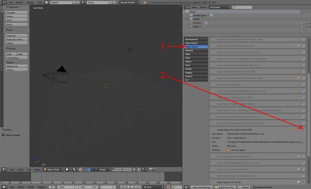
Blender will take us back to the main view with the Addons panel, and we can find the new addon in the Import-Export category (1) and enable it by selecting its checkbox (2).
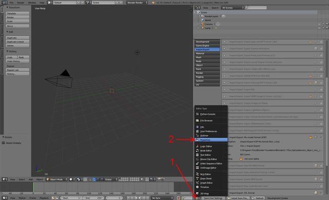
Now that that's done, let's return this section of the screen back to the Properties pane by selecting the current editor type button (1) and selecting Properties (2).
You don't need to restart Blender, everything is ready now for us to import our KSP model.
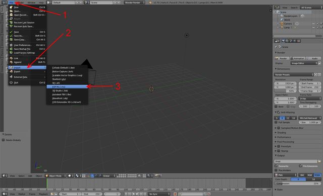
Click the File menu (1), select Import (2) and choose the KSP Mu format (3).
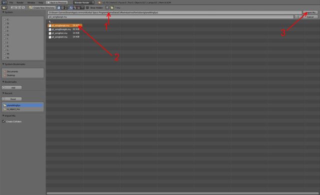
We're once again back to the file viewer scene so navigate to your model's location (1) select the model (2) and click the button (3) or double-click the file to load it up.
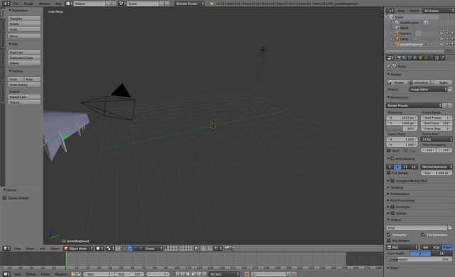
Success! For this tutorial, I have chosen to derive values for the Coffee Industries swept wing, as it offers up several good examples of how to properly handle a FAR aerofoil you won't see in other, more basic parts.
Also, because I want to use it in FAR! :p
Alright, first thing we need to do is isolate the main aerofoil mesh.
Use the middle mouse button to pan the camera around for a better view and use the right-click button to select the large main mesh area.
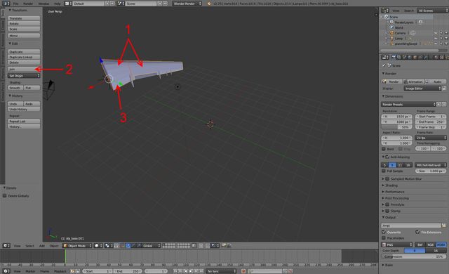
Turns out, this model has two separate meshes for the main wing. No problem - with one of the meshes selected, simply hold down the Shift key and right-click to select the other section of wing mesh as well (1).
Now let's click the Join button (2) to merge the two meshes into one for easier handling throughout this tutorial.
Finally, grab the green Y-axis handle (3) and drag with the mouse to translate the model only in this dimension, across the plane, and separating it from the control surface (and any other meshes that may be included in the model, which you can delete if you want).
Another method is to bring the entire model to the center of the scene with Alt+G, and then separate what you want, delete what you don't.
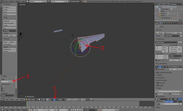
Next, let's lay the wing flat by selecting the axis rotation (1) and grabbing the red X-axis handle (2).
Drag the mouse a bit to start the rotation and you'll see the Translate panel to the left change to Rotate and you can then directly edit the angle value (3).
This can also be done by pressing R, then X, entering 90 and pressing Enter.
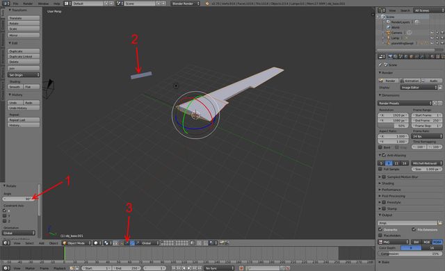
So let's make the angle 90 (1) so the mesh is flat. Now right-click to select the control surface you left behind (2), switch back to translation mode (3) and move that over near the main wing.
Repeat the previous steps to lay it flat out as well.
Let's now switch to Top Orthographic view (NUM7) so we can look directly down upon the meshes for our measurements.
While in this view, hold Shift while pressing the middle mouse button to drag the camera around.
If you simply middle-mouse drag the view will rotate back into User Perspective. If this happens, just NUM7 it again to return to Top Orthographic.
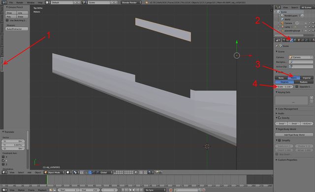
It's measuring time! Get out your meter stick by selecting the Grease Pencil pane (1).
But wait - it's not a meter stick unless you tell Blender you want it to be a meter stick, so click on the Scene button (2) and select Metric for units (3).
Now, before we go further there's a very important thing you must do.
Go to the part.cfg file for the model you are measuring and check the value for rescaleFactor.
If this value is missing or set to 1, then you don't have to do anything.
However, if this value is set to anything other than 1, you need to make sure you enter this into the Scale box in Blender (4).
For this model, the author scaled the part up 1.118x.
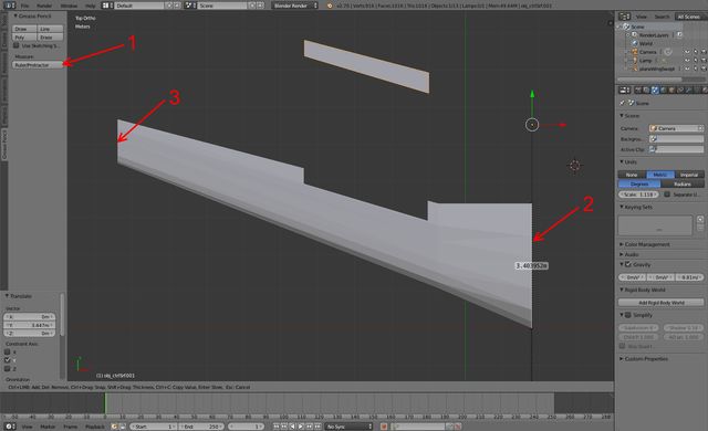
Okay, now we're ready to measure. Click the Ruler/Protractor button (1) and then click and drag in the scene to draw a line that will be measured out by Blender in the units and scale you specified.
The first values we will go after are the Root (2) and the Tip (3) of the aerofoil.
These are measured straight up or down as shown in (2), and it's easy to follow the lines of the mesh.
Some wings may have rounded ends, in which case you will want to use the grid lines for assistance, as we will see later.
To re-draw a ruler, you either have to hit Esc and then reselect the Ruler/Protractor, or grab the existing start/end point and drag them each to a new location.
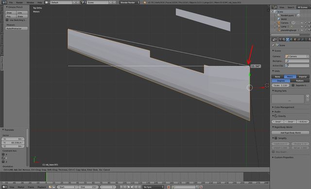
The next values we will go after are the Sweeps - Leading and Trailing.
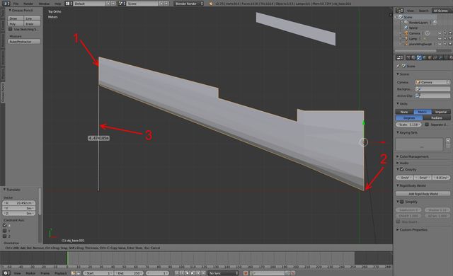
First you want to use the translation handles to move the mesh so the Tip aligns with a vertical grid line (1).
Now you want to place the intersection of the Leading Edge and Root (2) also on a grid line, or axis line.
Now you can draw a ruler (3) straight down from the top of the Tip to where the top of the Root would be, using the grid lines for reference.
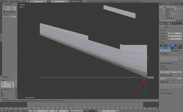
Now grab anywhere along the ruler and start dragging to activate the protractor function.
Drag the X over to the intersection of the Leading Edge and Root top and you will get the angle of the Leading Sweep.
We're going to take similar steps to get the Trailing Sweep.
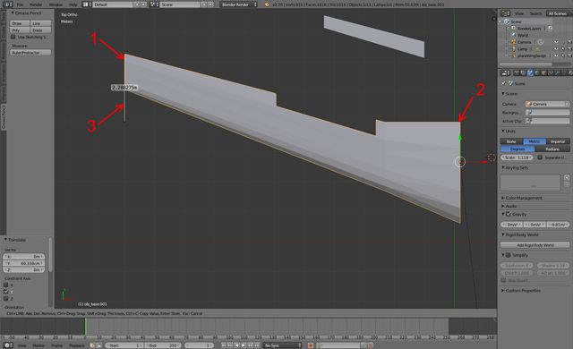
Keeping the Tip aligned with a vertical grid line (1), move the intersection of the Trailing Edge and Root (2) up to a horizontal grid line.
Now you can draw a ruler (3) from the base of the Tip down to where the base of the Root would be.
Note that this wing has a flat leading edge for a few meters before the sweep begins, but that doesn't matter to FAR.
For FAR the Trailing Sweep will always begin at the Root (remember - trapezoids).
Just like for the Leading Sweep, grab anywhere along the ruler and drag out the protractor - this time to the intersection of the Trailing Edge and Root base.
You now have the value for the Trailing Sweep.
Almost there!
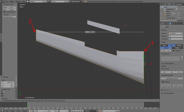
The last value every FAR aerofoil must have defined is the length from Root to Tip.
Because of the sweep, drawing a straight line from Root to Tip is difficult, but that's where the grid lines come to the rescue once again, by allowing us to align the Root (1) and then drawing a ruler from the Tip (2) along a horizontal grid line to the Root's vertical location.
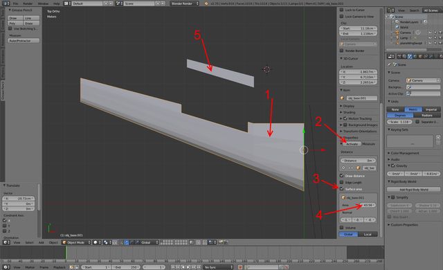
Last but not least, if the aerofoil you are measuring has a control surface, you have to do an additional step to find the value for CtrlSurfFrac.
This is where the Measure Panel plugin we activated earlier comes into play.
Press N to bring up the panel in which this tool resides (scroll to the bottom).
Right-click to select the main wing mesh (1) and then Activate the plugin (2).
Although this Activate button may come back in a session, unless you close and reload Blender it only needs to be pressed once.
Now select the Surface area box (3) and you will be given the surface area in square meters for the main aerofoil (4).
Once you've made note of this measurement, right-click to select the control surface (5) and then un-check and re-check the Surface area box (3) to refresh the measurement (4).
You can now divide the surface area of the control surface by the surface area of the main aerofoil to get the value for CtrlSurfFrac.
You now have all the measurements you need to derive values for the properties of the aerofoil required by FAR, using the equations diagram at the top of the tutorial.
The FAR ReadMe includes information about the FAR modules that you need to fill out with this data, but for examples sake here is the final Module Manager 2.x.x configuration for the swept wing model used in this tutorial:
@PART[planeWingSweptN]:NEEDS[FerramAerospacResearch|NEAR]
{
  // zero out all stock values, remove stock module
  @module = Part
  @maximum_drag = 0
  @minimum_drag = 0
  @angularDrag = 0
  @dragCoeff = 0
  @deflectionLiftCoeff = 0
  @ctrlSurfaceRange = 0
  @ctrlSurfaceArea = 0

  // add custom FAR values
  MODULE
  {
    name = FARControllableSurface // or FARWingAerodynamicModel for non-controllable wings
    MAC = 2.32  // Tip = 1.23m | Root = 3.4m
    MidChordSweep = 16.67 // Leading sweep 21.8* | Trailing sweep 11.54*
    b_2 = 11.19 // Root to tip in meters
    TaperRatio = 0.36 // Ratio of tip chord to root chord
    nonSideAttach = 0  // 0 for canard-like / normal wing pieces, 1 for ctrlsurfaces attached to the back of other wing parts
    maxdeflect = 15  // Default maximum deflection value; only used by FARControlableSurface
    ctrlSurfFrac = 0.09 // wing surface area = 43.56 | control surface area = 3.796
  }
}
Post in the FAR thread.
Now go out and make your favorite non-FAR-compatible parts work with FAR! (And share it with everyone!!)


