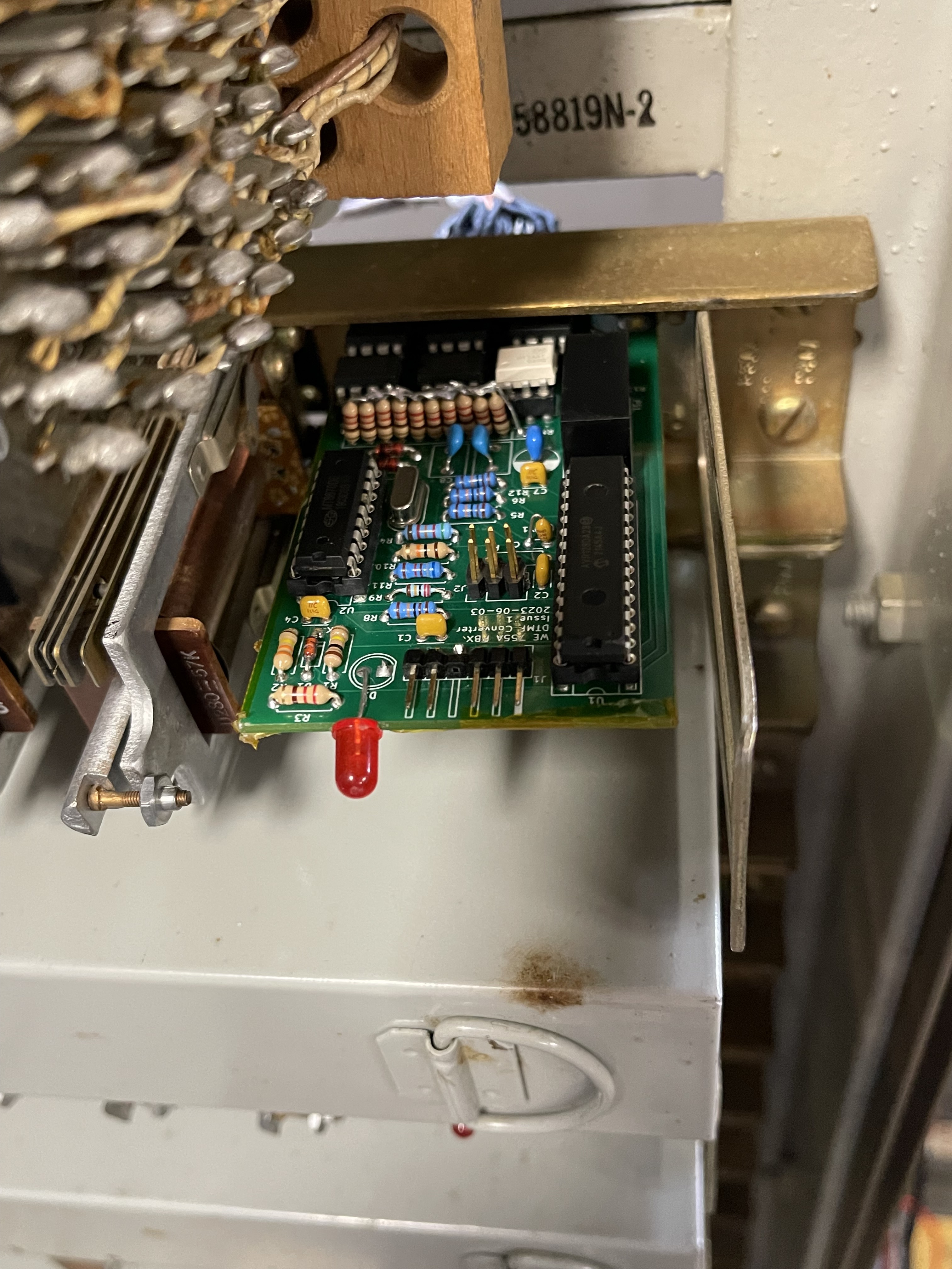
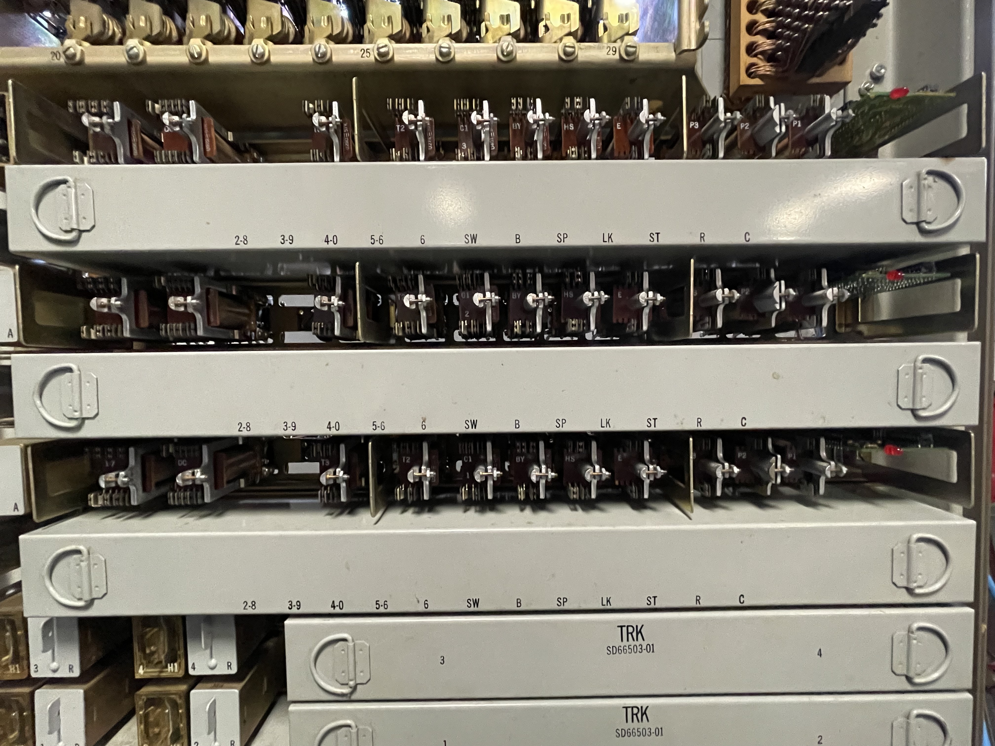
The Western Electric 755A PBX was designed in 1938 and supports pulse dialing only This DTMF converter adds support for Touch-Tone dialing. One DTMF Converter board needs to be installed in each of the three links. The converter recognizes DTMF digits, and sets the pulse counting relays in the link to the terminal count for the number dialed. This is not a tone to pulse converter, and operates much faster than one.
The dial plan for the 755A PBX consists of local station extensions 20-29 and 30-39. Although this PBX supports four trunks, they are not directly accessible by stations; instead, key stations with individual trunk pickup keys are used to select the trunks.
Here is an introductory video of the 755A PBX in operation.
This project builds upon the OKI AC125A DTMF Converter designed several years ago. While the OKI is an electromechanical crossbar PBX similar in some ways to the 755A, the OKI is about 40 years more modern.
Three boards have been assembled and installed in each of the 755A’s links. They work as intended for station to station and conference calls.
The DTMF converter employs digit translation as follows:
| First Dialed Digit | 755A Extension | Description |
| 0 | 20 | Operator |
| 1 | - | No operation |
| 2 | 2x | Direct-dialed 755A stations. |
| 3 | 3x | Direct-dialed 755A stations. |
| 4, 5, 6, 7 | - | No operation |
| 8 | 26 | Ringdown extensions 26, 27. |
| 9 | 36 | Ringdown extensions 36, 37 |
| Pin | Description | Ribbon Cable Color | Cloth Wire Color | 755A Link Connection |
| 1,2 | GRD | Brown/Red | Black | Connect to the B relay coil so the converter powers up when the link is active. |
| 3 | LINK_SPARE | Orange | ||
| 4 | LINK_C1 | Yellow | Or/Sl | |
| 5 | LINK_6 | Green | Sl/W/R | |
| 6 | LINK_5-6 | Blue | SL/W | |
| 7 | LINK_4-0 | Violet | Br/R | |
| 8 | LINK_3-9 | Slate | Br | |
| 9 | LINK_2-8 | White | Gr/R | |
| 10 | LINK_1-7 | Black | Gr | |
| 11 | LINK_T3 | Brown | Or/R | |
| 12 | LINK_T2 | Red | Or | |
| 13 | N/C | Orange | ||
| 14 | N/C | Yellow | ||
| 15 | N/C | Green | ||
| 16 | LINK_E | Blue | Blue | |
| 17 | Tip | Violet | O/GR | |
| 18 | Ring | Slate | O/GR-R | |
| 19,20 | -24VDC | White/Black | Red | -24VDC (Red) |
From SD-66611-01:
-BAT: Pick up from P1 relay red lead.
GRD: Pick up from B relay coil.
LINK_B: (Blue) Pick up from B relay coil (Upper left terminal.)
Tip: (Violet): Pick up T from 2mF capacitors on lower right corner (looking at from rear):
Ring: (Slate): Pick up T from 2mF capacitors on lower right corner (looking at from rear):
LINK_T2: (Red) Pick up from T2 relay coil.
LINK_T3: (Brown) Pick up from T3 relay coil.
LINK_C1: (Yellow) Pick up from C1 relay coil.
The 755A DTMF converter’s ground supply is connected to the B relay coil in the link so that the DTMF converter is only powered on when the link is active. This is necessary so that the first and second digits dialed can be properly identified if the calling station hangs up after dialing only a single digit.
When a station goes off hook, the link allotter selects an idle link, operating the link’s B relay. This powers up the DTMF converter, which waits for digit(s) to be dialed. If the first dialed digit is 2 or 3, the converter waits for a second digit to be dialed and then activates the tens and units counting relays to their terminal count. If the first digit is a digit other than 2 or 3 is dialed, the digit is handled as follows:
- 1, 4, 5, 6, or 7: Ignored
- 0, 8, 9: Translated to a 2-digit extension that is dialed immediately.
After dialing is complete, further dialing is disabled until the called station answers and hangs up again. This is needed to prevent operation of the pulse counting relays during an established call, while also supporting conference calling.
Conference calling with the 755A works as follows:
- The originating station calls an extension.
- The extension answers the call, activating the E relay.
- The originating station asks the answering station to hang up momentarily so that a conference call can be established.
- After the called station hangs up, the originating station dials the number of an additional station to join the conference.
- After the first digit of the called number is dialed,
| Digit | Relays Activated | Note |
| 2 | T2 | T2 activated stops dialtone. |
| 3 | T2 and T3 |
| Digit | Relays Activated | To finish dialing |
| 1 | C1, 1-7 | Release C1 |
| 2 | C1, 2-8 | Release C1 |
| 3 | C1, 3-9 | Release C1 |
| 4 | C1, 4-0 | Release C1 |
| 5 | C1, 5-6 | Release C1 |
| 6 | C1, 5-6, 6 | Release C1 |
| 7 | C1, 1-7, 6 | Release C1 |
| 8 | C1, 2-8, 6 | Release C1 |
| 9 | C1, 3-9, 6 | Release C1 |
| 0 | C1, 4-0, 6 | Release C1 |
| T | Tip | ||
| R | Ring | ||
| E | Call Active (Interrupt the microcontroller.) | ||
| T2 | Tens Digit 2 (Breaks dial tone.) | ||
| T3 | Tens Digit 3 (Also requires T2 activated.) | ||
| 1-7, 2-8, 3-9, 4-0, 5-6, 6 | Units Digit Selection | ||
| C1 | Activated before Units selection relays are set, released when the digit is complete. | ||
| Q3:0 | DTMF Digit Selection | ||
| StB | DTMF Valid Strobe (Interrupt to microcontroller.) | ||
Online DigiKey BOM. Interactive BOM.
| Quantity | Reference Designator | Value |
| 4 | C1, C2, C4, C7 | 0.1uF |
| 1 | C3 | 0.01uF |
| 2 | C5, C8 | 0.01uF/630V |
| 1 | C6 | 10uF 25V |
| 1 | D1 | 1N4148 |
| 1 | D2 | LED |
| 2 | D3, D4 | 1N4734A |
| 2 | F1, F2 | Fuse 630mA |
| 2 | H1, H2 | MountingHole |
| 1 | J1 | Conn_01x06_Male right angle |
| 1 | J2 | UPDI (2x3 pin header) Straight |
| 1 | J3 | Conn_02x10_Odd_Even |
| 1 | PS1 | SPBW06 |
| 1 | R1 | 100K |
| 1 | R2 | 330K |
| 1 | R3 | 220 |
| 1 | R4 | 52.3K 1% |
| 4 | R5, R6, R8, R12 | 110K 1% |
| 1 | R7 | 4.7K |
| 1 | R9 | 220K 1% |
| 1 | R10 | 10K |
| 1 | R11 | 68.1K 1% |
| 1 | R13 | 1.5K |
| 1 | RN1 | 220 |
| 1 | U1 | AVR128DA28-I/SP or AVR128DA28-E/SP |
| 1 | U2 | MT8870 |
| 1 | U3 | H11AA1 |
| 5 | U4, U5, U6, U7, U8 | LAA108 (or LAA110L or CLA170) |
| 1 | Y2 | 3.579545MHZ |


