-
Notifications
You must be signed in to change notification settings - Fork 1
OBI socket
- Hardware
- Powering the Device
- Adding a Serial Interface
- Flashing the Device
- Setting up the Device
- Setting up the wifi client
The hardware used is a 9€ power socket I bought from a hardware store ('OBI') in Germany. It seems to be a newer revision than the other OBI wifi sockets I found on the interwebs. The plastic case says something about EUROMATE GmbH.
To open the case your best option is a tri-wing bit. Or a power drill.
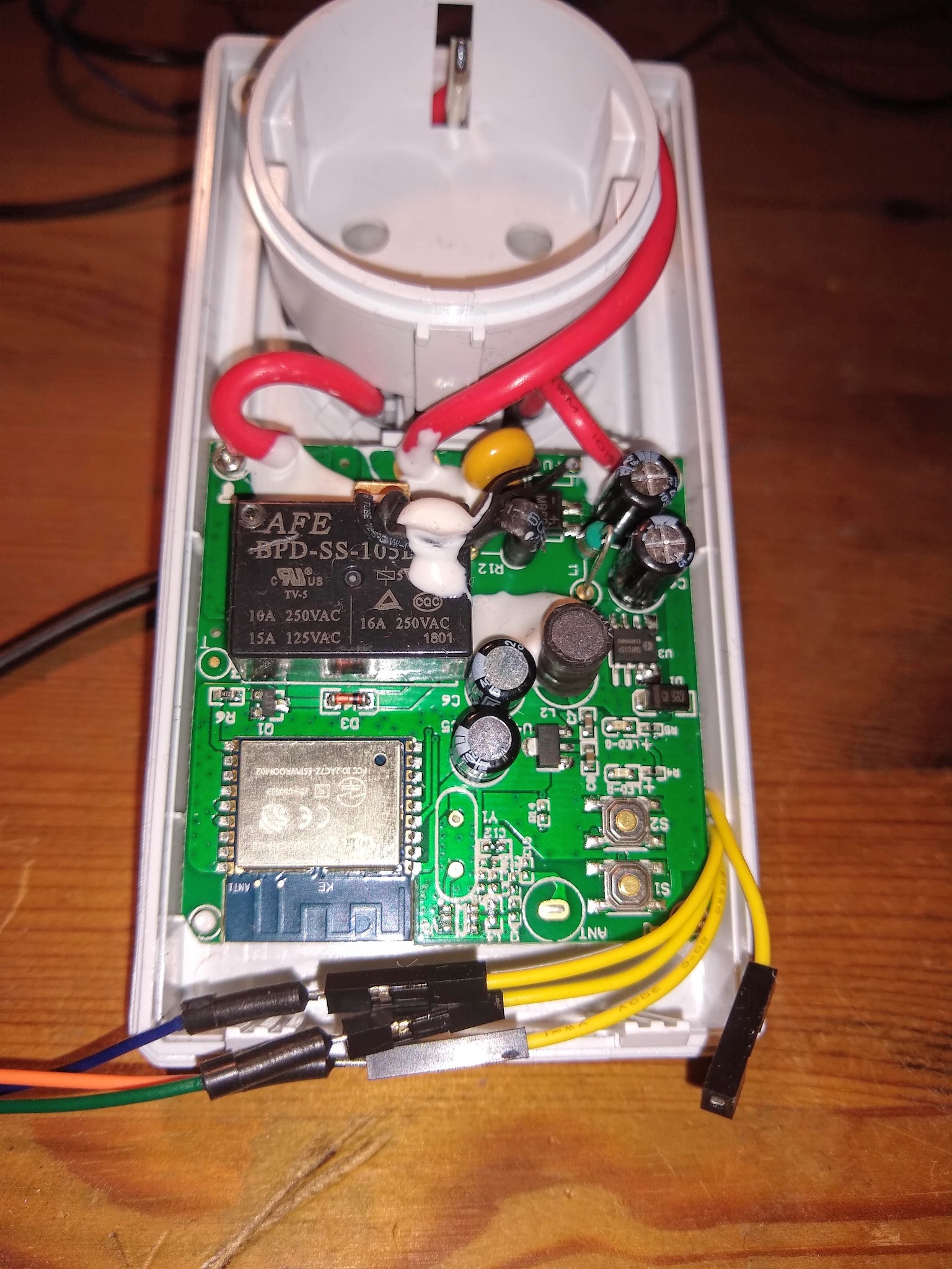
The design is based around an ESP8266 WROOM-02 module (Datasheet).
On the supply side there is an SM7035P buck converter supplying ~5V to the relay coils and a 1117 LDO for 3,3V supply.
| ESP Port | Desc. |
|---|---|
| IO5 | S1, On/Off switch |
| Reset | S2, reset |
| IO12 | green LED |
| IO13 | red LED |
| IO4 | relay |


During development / flashing connect a cable to the solder points marked with 5V in order to power the ESP in a safe way when the socket's case is open. Using the 5V supply (120-150mA will be enough) ensures that the relay will work.
Another option is probably to supply 3.3V directly to the solder point marked with 3.3V but I haven't tested that. Of course, the relay will not work in this case.
If you are brave (or stupid) you can also power the socket directly from mains.
However...
Much safer: Supplying 5V to the 5V pin (or the high side of the 1117, the cathode of D1 or pins 7/8 of SM7035P).
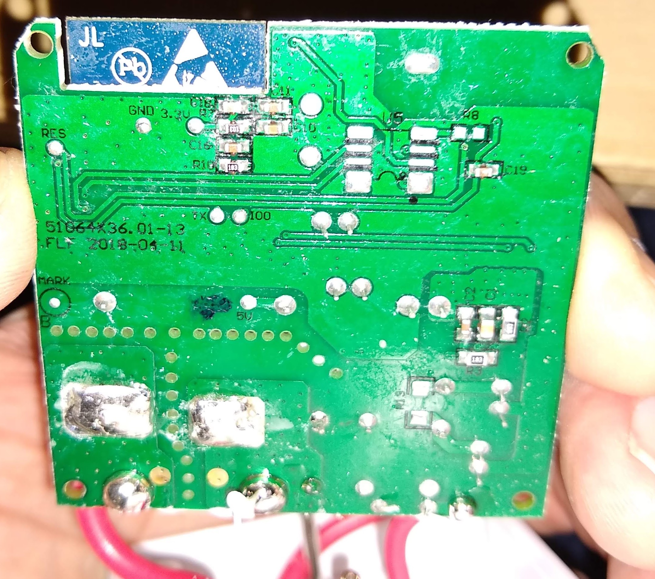
As you can see, there is no obvious serial port connection available. But the designers were kind enough to provide connections on the bottom side of the pcb that are easy to solder.
In addition to RX/TX/GND (from top to bottom) you are going to need a wire connected to IO0.
IO0 is required to be pulled to GND during reset (S2) in order to put the ESP into UART download mode. E.g. by briefly connecting it to the ESP8266 shield.

I used breadboard jumper cables. The 5V cable is missing in the photo, I added it a bit later... ;-)


-
Connect serial port (RX/TX/GND)
-
Pull IO0 to GND during reset
-
I'm using
/dev/cu.usbserialin the following commands, this may vary depending on the device you are using. -
Optional - Backup flash:
esptool.py --port /dev/cu.usbserial --baud 460800 read_flash 0 2097152 orig_fw.bin
- Erase flash:
esptool.py --port /dev/cu.usbserial --baud 460800 erase_flash
- Flash micropython:
esptool -p /dev/cu.usbserial --baud 460800 write_flash 0 firmware-combined.bin
If you are getting errors, try a lower baud rate (230400 or 115200).
This firmware image is based on micropython 1.9.4 and already includes Picoweb and umqtt (robust and simple) as frozen byte code.
This is basically taken from micropython documentation
Setup webrepl on the esp via serial connection, (my serial port is /dev/cu.usbserial, change it to whatever device you are using)
screen /dev/cu.usbserial 115200
Now enable/set up webREPL:
import webrepl_setup
Enable the demon and provide a password.
In order to copy files over wifi you need to clone https://github.com/micropython/webrepl
Edit cp_esp.sh according to your serial port and the password you provided.
Replug/reset the ESP.
Once the system is flashed with micropython and restarted the socket will show up as an wireless access point with the name MicroPython-AABBCC (AABBCC are the last 6 digits of its MAC address). The default password for the WiFi is micropythoN (capital 'N').
Now you can either use the webREPL page or ./cp_esp.sh *.py to transfer the python files to the ESP.
Don't forget to copy the .css file into the static folder on the ESP as well.
Create static folder on ESP (picoweb seems to require that in order to serve css files):
import os
os.mkdir(’static’)
Copy css file to ESP via webrepl_cli:
./cp_esp.sh static/mini-default.css
Restart the device and the web-app should start.
Now the socket opens up an access point for initial configuration with the name "obi-socket-AABBDD". Connect to it with the password "myobiPassword". You can change the default password in config.py. Its IP address will be 192.168.4.1 once you connect to its network.
Browse to http://192.168.4.1/setup and enter the wifi client wifi_ssid, wifi_pw and restart the device.
Once the the socket reboots it will flash the green LED while trying to connect (timeout is about 10 seconds). If the wifi client connection succeeds, the green LED will light up continuously and access-point mode is stopped.
Depending on your dhcp server setup the socket can now be addressed at http://obi-socket-xxyyzz (or whatever hostname you provided during setup).
To reset/delete the wifi config press the ON/OFF button for about 10 seconds until the red LED starts flashing and the socket will reboot to setup-mode (access-point available).