Tutorial
This chapter explains the Emfrp's roles on developing embedded systems.
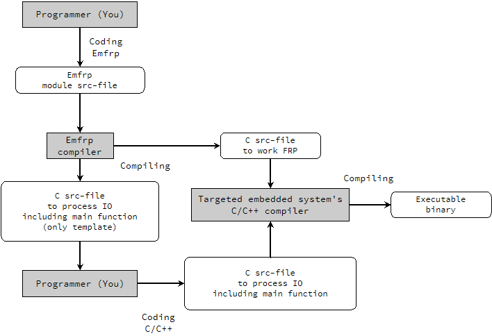
All you (programmer) need to do are:
- writing Emfrp module which is the code of system's logic along with FRP abstraction and
- writing IO code in C/C++.
What Emfrp's compiler does are:
- reading the Emfrp module code you wrote and compile it into an ANSI-C src-file and
- generating an ANSI-C src-file including a main-function for you to write IO code.
The following image is visualization of these.
When seen from outside, the module is a something like function having multiple inputs, multiple outputs, and memory of states.
As an example, Sum module which accumulates input values can be defined:
- Input is single integer value.
- Output is single integer value which is sum of so far inputs.
Note that this module implicitly has memory of state which is output value of last time.
The behavior of Sum module can be illustrated as follows:

Open your text editor and write following code. (You can use syntax-highlight on TextMate or Atom.)
module Sum
in inp : Int
out sum
use Std

node init[0] sum = sum@last + inp
Finishing to write, save it as Sum.mfrp.
Then, compile it by emfrp.
$ emfrp Sum.mfrp
Sum.c, Sum.h and SumMain.c ought to be generated on your current directory.
The, open SumMain.c and confirm following code is generated.
#include "Sum.h"

void Input(int* inp) {
  /* Your code goes here... */
}
void Output(int* sum) {
  /* Your code goes here... */
}
int main() {
  ActivateSum();
}
Write IO code as follows.
#include "Sum.h"
#include <stdio.h>

void Input(int* inp) {
  scanf("%d", inp);
}
void Output(int* sum) {
  printf("%d\n", *sum);
}
int main() {
  ActivateSum();
}
Compile Sum.c and SumMain.c by C-compiler.
$ cc Sum.c SumMain.c
Execute compiled binary.
$ ./a.out
By feeding inputs 1, 2, 3..., you will see same output with former illustration.
Let's make a digital clock application.
In the following explanation, if you have any questions about Emfrp's syntax, see Emfrp documentation.
At first, define module's IO.
module LCDClock
in
  btnMode(False) : Bool,   # Is mode-button pushed now?
  btnNext(False) : Bool,   # Is next-button pushed now?
  btnRotate(False) : Bool, # Is rotate-button pushed now?
  pulse100ms : Bool        # input to be True only once per 100ms
out
  hour, min, sec,            # current time to display
  maskHour, maskMin, maskSec # Is it now needed to display -- instead of two-digits?
use
  Std
Then, define some data-types and functions for comfortable programming.
type Mode = Normal | Edit
type TPos = HPos | MPos | SPos
type Time = Time(Int, Int, Int)

func nextMode(m) = m of Normal -> Edit, Edit -> Normal

func editable(m) = m of Normal -> False, Edit -> True

func nextPos(p) = p of HPos -> MPos, MPos -> SPos, SPos -> HPos

func positiveEdge(a, b) = !a && b

# proceed Time by 1sec
func proceedTime(t) = {
  Time(h, m, s) = t
  newS = s + 1
  newM = m + (newS / 60)
  newH = h + (newM / 60)
  Time(newH % 24, newM % 60, newS % 60)
}

func roundingTime(t, dh, dm, ds) = {
  Time(h, m, s) = t
  Time((h + dh) % 24, (m + dm) % 60, (s + ds) % 60)
}
Define nodes about timing.
# mod-10 counter incremented by every 100ms
node init[0] counter : Int =
  (if pulse100ms then counter@last + 1 else counter@last) % 10

# time-varying value to be True only once per 1sec
node pulse1s : Bool =
  counter == 0 && counter@last != 0

# time-varying value switching True/False by every 500ms
node flash : Bool =
  counter < 5
Define nodes about time-set mode.
# time-varying value representing current time-set mode
node init[Normal] curMode : Mode =
  if btnMode@last `positiveEdge` btnMode then [email protected] else curMode@last

# time-varying value representing current editing-cursor-position
node init[HPos] curPos : TPos =
  if btnNext@last `positiveEdge` btnNext then [email protected] else curPos@last
Define the nodes for setting time.
# time-varying value representing diffs to add to current time.
node (dh, dm, ds) : (Int, Int, Int) =
  if curMode.editable && (btnRotate@last `positiveEdge` btnRotate) then
    curPos of:
      HPos -> (1, 0, 0)
      MPos -> (0, 1, 0)
      SPos -> (0, 0, 1)
  else
    (0, 0, 0)
Finally, define the nodes representing current time and need of masking.
# time-varying value representing current time
node init[Time(0, 0, 0)] Time(hour, min, sec) as curTime =
  if pulse1s then
    [email protected](dh, dm, ds)
  else
    [email protected](dh, dm, ds)

# time-varying value representing need of masking
node (maskHour, maskMin, maskSec) =
  if curMode.editable && flash then
    curPos of:
      HPos -> (True, False, False)
      MPos -> (False, True, False)
      SPos -> (False, False, True)
  else
    (False, False, False)
Finished writing all of the above codes in one file, save the file as LCDClock.mfrp and compile it by emfrp.
Next, open a generated file LCDClockMain.c and write IO code in C/C++ to fit in your target embedded system.
Following is one example IO code for mbed LPC1768 with application board.
#include "LCDClock.h"
#include "mbed.h"
#include "C12832_lcd.h"

C12832_LCD lcd;
Ticker t;
DigitalIn center(p14), up(p15), right(p16);
int pulse100_flag = 0;

void timer_callback() {
  pulse100_flag = 1;
}

void display(int n, int mask, char c) {
  if (mask) {
    lcd.printf("--%c", c);
  } else {
    lcd.printf("%02d%c", n, c);
  }
}

void Input(int* btnMode, int* btnNext, int* btnRotate, int* pulse100ms) {
  *btnMode = center.read();
  *btnNext = right.read();
  *btnRotate = up.read();
  *pulse100ms = pulse100_flag;
  pulse100_flag = 0;
}

void Output(int* hour, int* min, int* sec, int* maskHour, int* maskMin, int* maskSec) {
  lcd.cls();
  lcd.locate(45, 10);
  display(*hour, *maskHour, ':');
  display(*min, *maskMin, ':');
  display(*sec, *maskSec, '\n');
  wait(0.01);
}

int main() {
  t.attach(&timer_callback, 0.1);
  ActivateLCDClock();
}
As finishing, compile LCDClock.c and LCDClockMain.c by C/C++ compiler for your embedded systems and write compiled binary to the system.
It may work as the former video.