-
Notifications
You must be signed in to change notification settings - Fork 29
Section 3.3 Assembly of the XZ Unit Mounting the Timing Belt
|
|
|
|
|
|
|
|
|
-
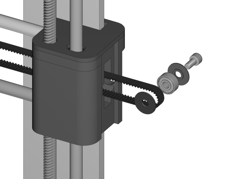
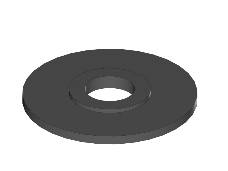
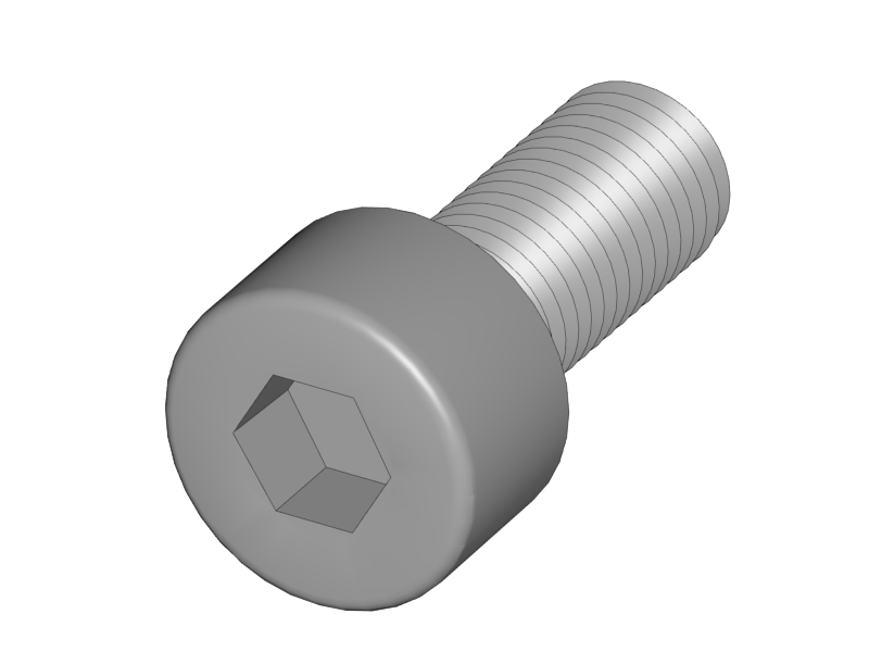
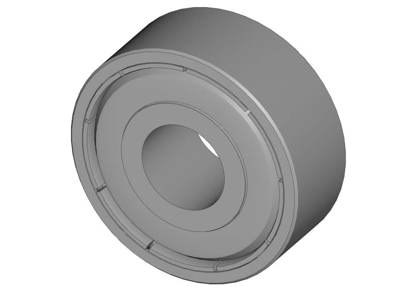
Put the bearing onto the M4 screw with a Belt Guiding Disc on both sides
-
Make sure that the little notch of the discs is facing the bearing. The smooth surface is facing outwards.
-
-
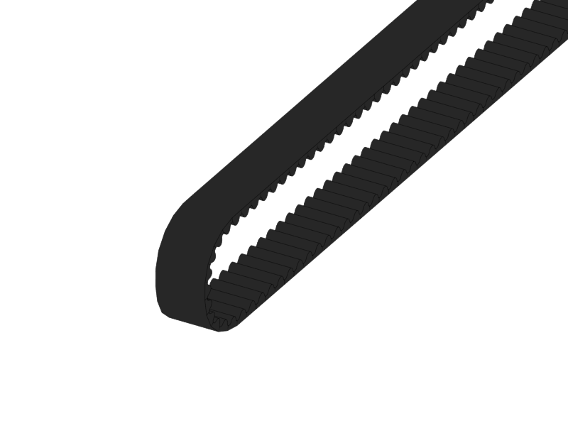
Lead the timing belt throught the opening of the X-Idler holder.
-
Put the bearing assembly throught the loop
-
Pull it back into the X-Idler holder.
-
You just slide in the idler bearing with screw from the side. No need to screw anything, the tension of the belt will keep the bearing in its place.
-
|
-
Push one end of the timing belt into the teeth of the X-Axis
-
Lead the remaining long side through the opening underneath the Teeth.
-
Loosen the screws of the X-Motor a little bit, and slide the motor some millimeters in the direction of the X-Carriage.
-
Lead the timing belt over the motor pulley
-
Lead it back into the direction of the X-Carriage.
-
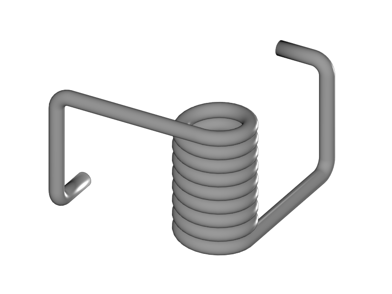
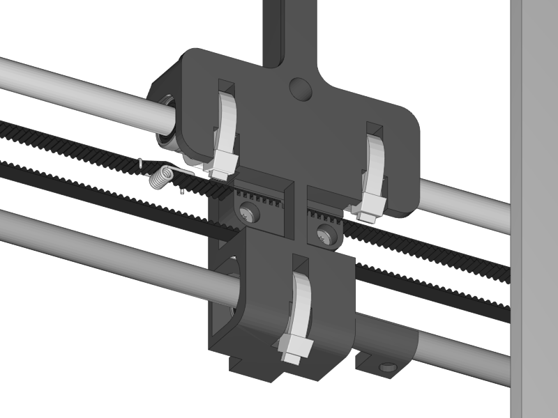
Put the Belt Tensioner on the belt as shown.
-
Push the remaining end of the timing belt into the X-Teeth.
-
Set the tension not too tight.
-
Tighten the timing belt by sliding the motor to the right and fix it again with its screws.
-
If the belt moves up and down a little when you move the X-Carriage the belt is too loose
-
If the belt makes sound like a guitar string, it is too tight.
-
-
If the belt tensioner is (almost) straight as shown the tension is right.
|
|
|
|
|
|
|
|
|
|
|
|
|
-
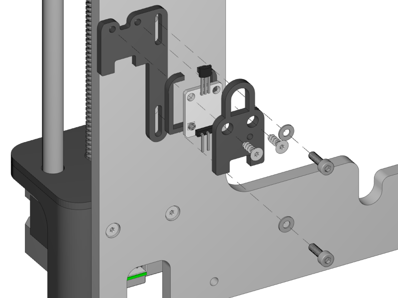
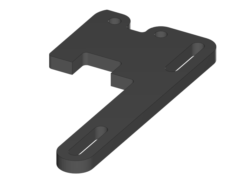
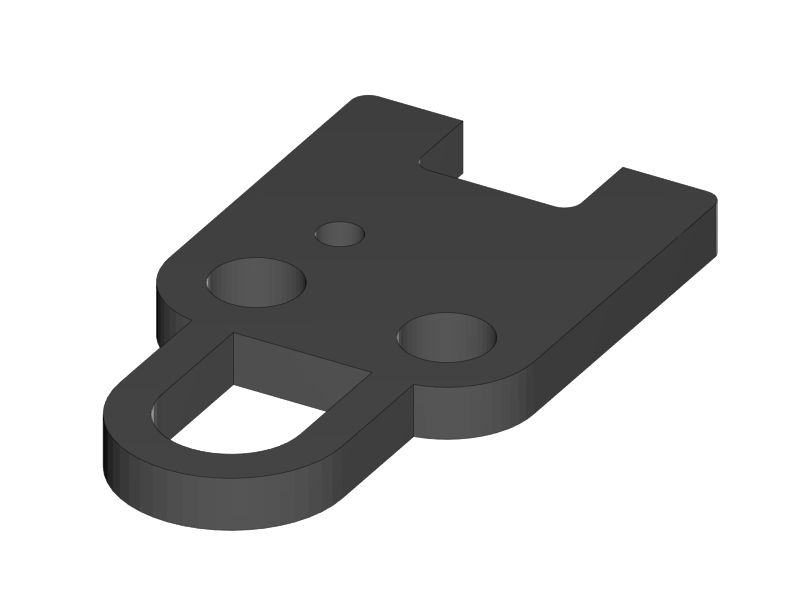
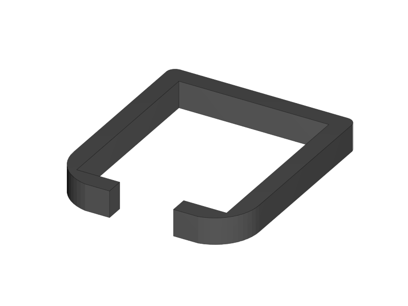
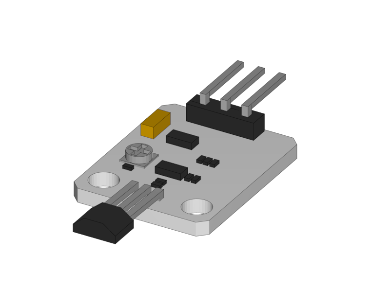
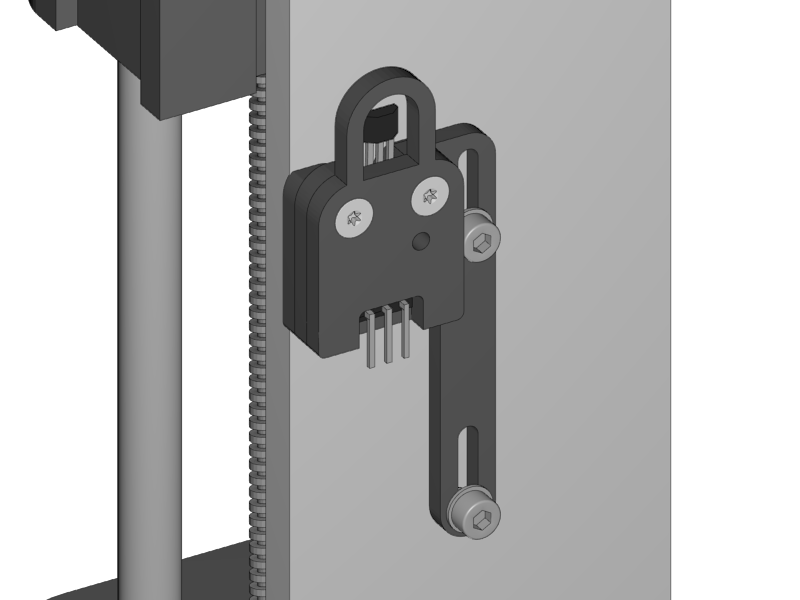
Mount the end-stop and with its cover onto the Z-Endstop holder with the Torx screws.
-
Be carefull to not tighten the screws too much.
-
-
Mount the Z-Endstop assembly onto the backside of the aluminium frame in the most upper position.
-
Mount the Z-Endstop in the upper position as shown below.
|
|
|
-
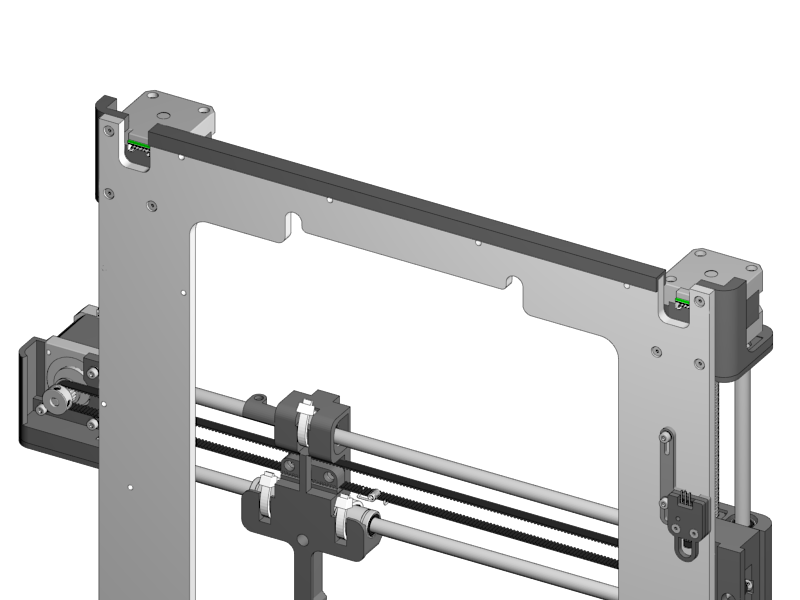
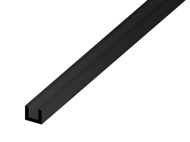
Put the rubber strip to the bottom of the XZ-Frame with some drips of super glue.
1 Introduction
1.1: History
1.2: Tools and Parts
1.3: Preparing the Casings
2 Assembly of the Y-Unit
2.1: Rods and Power Supply
2.2: Front- and Back- Plate
2.3: Mounting Y-Carriage and Belt
3 Assembly of the XZ-Unit
3.1: Mounting the X-Axis
3.2: Mounting the Z-Axis
3.3: Mounting the Timing Belt
3.4: Assembling the Extruder
4 Wiring
4.1: Wiring the Power Supply
4.2: Wiring the Z-Unit
4.3: Wiring the Y-Unit
4.4: Wiring the X-Axis
4.5: Gluing the Endstop Magnets
4.6: Uploading Firmware
4.7: Wiring the Extruder
4.8: Mounting the Heatbed
5 Calibration
5.1: Testing Functionality
5.2: Calibrating the Y Axis
5.3: Calibrating the X Axis
5.4: Calibrating the Print Platform
6 Printing
6.1: Filament Holder
6.2: Cura
6.3: Kisslicer
6.4: Dual Printing
