-
Notifications
You must be signed in to change notification settings - Fork 20
Section 2.2 Assembly of the Y Unit Mounting the Front and Back Plate
|
|
|
-
Mount the pulley onto the motorshaft with the two little set screws. You can find these screws in the little white bag in the box of your RUMBA electronics.
-
The distance between the pulley and the motor is 8mm.
|
|
|
|
|
|
|
|
|
|
|
-
Mount the motor onto the Y-Motor Holder
-
Be sure that the motor connector is facing downwards.
-
Mount the end-stop with its cover. Don’t make the screws too tight.
-
Find the covers in the bag with Acrylic laser cut parts
-
-
In the little box of the end-stops you will find 6 little magnets: don’t loose them!
|
The result looks like this
|
|
|
-
Put the two glass fuses into the power connector
-
Connect the high voltage power cable to the Power connector as shown.
-
The connection might be stiff. Be patient and firm, but be careful not to break the power connector pins.
-
|
|
-
Be gentle with the aluminium plates. You don’t want to scratch them already.
-
Click the power connector into the Back Plate.
|
|
|
|
|
-
Pull the power cable through the hole on the left of the Power Connector Cover.
-
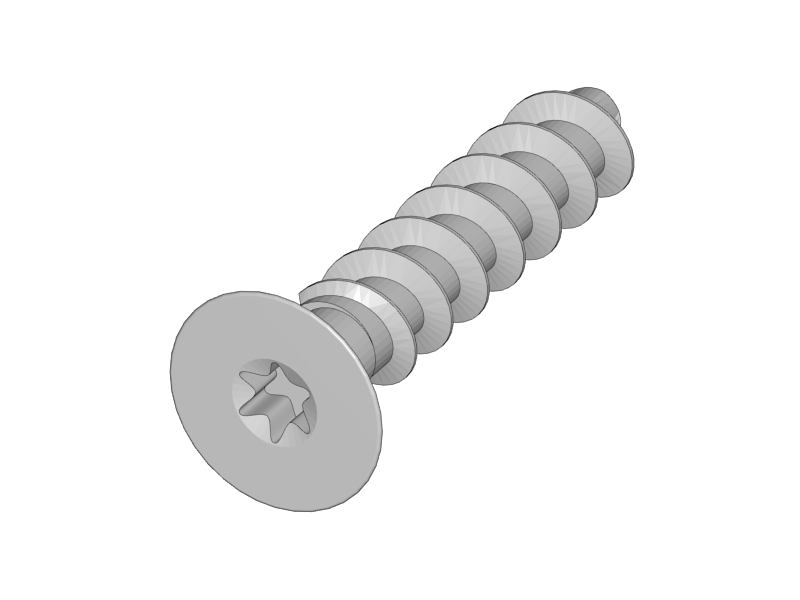
Mount the Power Connector Cover with the plastic screw.
-
The teeth washer should ensure electrical contact between the ground wire and the aluminium back plate.
|
|
|
-
Put the front plate onto the threaded rods.
-
Put the round nuts to the M10 Threaded rods. Do not fix the front plate yet.
-
Firmly hold the M10 rod and fix the round nut onto the M10 rod.
-
The front plate should still be loose now.
|
-
Fix the front plate by tightening the round nuts.
|
-
Tighten the M10 nuts on both sides of both Y-Middle parts
-
Make sure that both parts remain straight.
|
|
|
|
|
|
|
-
In general be careful with the aluminium parts and prevent scratches by putting a towel on the table.
-
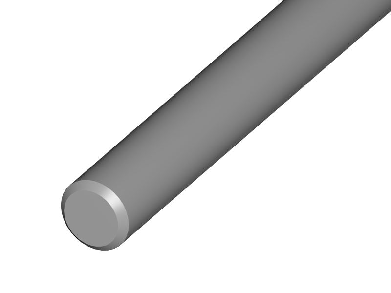
Test if the smooth rods can enter the hole in the aluminium plates. The holes in the aluminium plates are very accurate and the smooth rods might have a little bur from cutting them. If they don’t fit, carefully file of the edge of the rods a little bit until they all fit.
-
Put the linear bearings on the rods.
-
Put the Y-Motor Holder and the Y-Back Left part on the M10 threaded rods
-
Put the smooth rods on the front plate.
-
Mind that the right hand rod has two bearings, the left rod only one.
-
Make sure that the left hand rod enters the slot hole in the front plate through the slot hole of the Y-Height adjuster. With the height adjuster you will later make the two smooth rods perfectly parallel.
-
-
Put the Back Plate on the M10 Rods.
-
Tighten the round nuts and the corresponding M10 nuts in such a way that the back plate is nice and straight.
The result looks like this:
|
|
-
If you are having difficulties making the unit straight, see what happens when you loosen the M4 screw on the Power Supply, make the unit straight and fix it again.
##i3 Berlin
1 Introduction
1.1: History
1.2: Tools and Parts
1.3: Preparing the Casings
2 Assembly of the Y-Unit
2.1: Rods and Power Supply
2.2: Front- and Back- Plate
2.3: Mounting Y-Carriage and Belt
3 Assembly of the XZ-Unit
3.1: Mounting the X-Axis
3.2: Mounting the Z-Axis
3.3: Mounting the Timing Belt
3.4: Assembling the Extruder
4 Wiring
4.1: Wiring the Power Supply
4.2: Wiring the Z-Unit
4.3: Wiring the Y-Unit
4.4: Wiring the X-Axis
4.5: Gluing the Endstop Magnets
4.6: Uploading Firmware
4.7: Wiring the Extruder
4.8: Mounting the Heatbed
5 Calibration
5.1: Testing Functionality
5.2: Calibrating the Y Axis
5.3: Calibrating the X Axis
5.4: Calibrating the Print Platform
6 Printing
6.1: Filament Holder
6.2: Cura
6.3: Kisslicer
6.4: Dual Printing


