Pico MMU RatOS
by Rigattoni
-
You need to flash your additional EBB42 for the Pico MMU manually. Follow the instructions from: https://github.com/lhndo/LH-Stinger/wiki/Pico-MMU#mcu-protocol-error-firmware-mismatch-on-btt-ebb42
-
Follow the instructions below for setting up your printer.cfg and sp_mmu.cfg.
Note: this procedure uses the Setup Wizard only for its firmware flashing mode, and not for changing your main configuration
-
In Mainsail/Fluidd switch to the configurator and open the Setup Wizard.
-
If you already configured your printer completely, just skip the following page: "Configure Wi-Fi Setup".
-
On the next page: "Select your printer" choose "Rat Rig V-Core 4 IDEX". Size is not important.
--> A pop up will occur to ask : "How do you want to proceed?".
--> Choose: "Start fresh". Nothing will get changed, we need this step to get the second EBB42 available in the configurator. -
Skip the page "Pick Control board" and the following one "Pick T0 Toolboard".
Attention!: There is an error in the configurator, because the next page after "Pick T0 Toolboard" has the same name!!! -
On the second page "Pick T1 Toolboard", you will see the new EBB42 which needs to get flashed.
Follow the steps shown in the configurator to put the EBB42 in DFU mode. Then your new EBB42 can be flashed automatically. -
After successful flashing procedure you can close the configurator. DO NOT SAVE ANYTHING!!! Just switch back to Mainsail/Fluidd
-
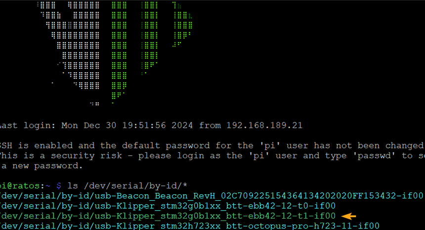
SSH to your Raspberry Pi
-
Run
ls /dev/serial/by-id/*to find the serial port of the board and copy the new found USB device.
As a V-Core user you already have an EBB42 mounted to your toolhead (toolboard T0). So it makes sense to connect your filament sensor to this toolboard.
This needs to get taken into account. So let´s have a look at the needed changes:
-
Update the newly flashed Pico EBB 42 serial in the line below:
You can find your serial by running:ls /dev/serial/by-id/*[mcu PICO_MMU] serial: /dev/serial/by-id/usb-Klipper_stm32***************************** -
Preparation for using the toolboard T0 which hosts the filament sensor pin:
[duplicate_pin_override] pins: toolboard_t0: PB3 ### Remark: look up the diagrams of your toolboard and choose the right port. -
Because the filament sensor has been connected to the toolhead toolboard T0, you need to change that accordingly in the following places:
[manual_stepper sp_motor] .... endstop_pin: ^toolboard_t0: PB3 # Filament Sensor pin - keep ^ pullup symbol .... [gcode_button sp_sensor] pin: ^toolboard_t0: PB3 # Filament Sensor pin - keep ^ pullup symbol .... [filament_switch_sensor sp_sensor_runout] switch_pin: ^toolboard_t0: PB3 # Filament Sensor pin - keep ^ pullup symbol .... -
Final steps:
Comment the [gcode_macro T] lines as illustrated below:

Add [include sp_mmu.cfg] just in front of the lines below.
Example:
[include sp_mmu.cfg]

# REMEMBER TO CALIBRATE YOUR BEACON!
# Run BEACON_RATOS_CALIBRATE for automatic calibration.

Finally press save and restart to overtake the settings.
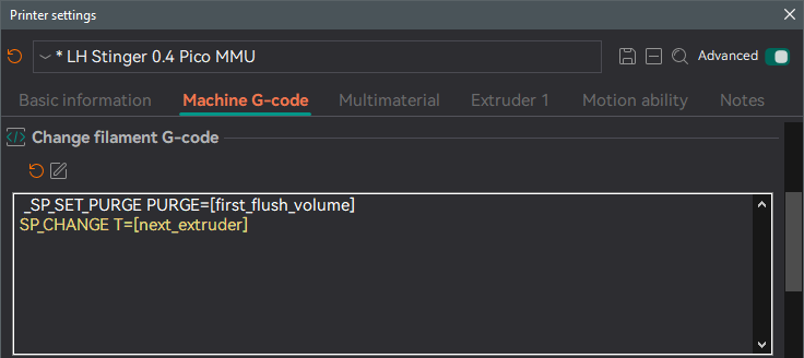
In addition to the slicer settings mentioned in the Pico MMU Guide, in the Change filament G-code section, add SP_CHANGE T=[next_extruder] under the _SP_SET_PURGE PURGE=[first_flush_volume] line.